Questions regarding the GB3 PCB
Marc,
I am the proud owner, thanks to you and Prasi, of both 9 and 8-pin sets of the PCB. Thanks so much to you both, and of coarse gingertube.
As I’m preparing for my first build I have a question and a request.
Question: I’m not sure which schematic you implemented in the PCB. Am I correct that you did post #602, rather than #604 in the gingertube thread? Did you prefer to take shunt feedback from the anodes rather than the UL taps? I realize it would take only a few simple changes to cut two traces and connect to the UL terminals if one wanted to implement the UL shunt feedback that Ian seemed to prefer, but I am curious if and how you determined that you prefer feedback from the Anodes.
Request: Could you suggest a proper heater jumper set (to switch from 12ax7 to 6n2p) for the BOM, please. I looked at Mouser, but I’m not sure what would work and fit correctly.
Regards and thanks very much,
F.
Last edited:
Francois,
I take the feedback from the anodes since the version from the screens did not give consistant result and was very dependent of the speaker. The PCB was made to help tubes newbies to build a tube amplifier as easily as a solid state amplifier, and I wanted to make a safe board without testing problem 🙂
I didn't put a heater jumper on the EL34 Baby Huey for the same reason : to make it a straightforward solution with less potential errors... But I have done it on a tube preamplifier and in the latest EL84 Baby Huey version following a demand on the forum 🙂
Best regards,
Marc
Attachments
Thanks for clarifying the choice of anode vs. screen UL shunt feedback.
I was hoping for a suggestion (Mouser part#) for the GB3 EL84 board, since the BOM omitted it and I could not identify a suitable part.
I was hoping for a suggestion (Mouser part#) for the GB3 EL84 board, since the BOM omitted it and I could not identify a suitable part.
I was hoping for a suggestion (Mouser part#) for the GB3 EL84 board, since the BOM omitted it and I could not identify a suitable part.
Hi Francois,
I use single row pin headers similar to this for Marc’s preamp board. Cut a section of three in a row and install, then jumper pins 1&2 or 2&3.
61301211121 Wurth Electronics | Mouser
The BOM include parts for both version 😀
Marc
Marc, You are not reading my question correctly. Smile!
The BOM does not include a Mouser number for the jumper. I’m asking for help with finding the jumper that you had in mind when you did the PCB layout, because I can’t.
Last edited:
Hi Francois,
I use single row pin headers similar to this for Marc’s preamp board. Cut a section of three in a row and install, then jumper pins 1&2 or 2&3.
61301211121 Wurth Electronics | Mouser
Thanks Vunce,
Very helpful. I hoped Marc would include the part he had in mind in the “official” BOM, but your pointer would certainly provide a good alternative.
Thanks.
I am ready to power up. What is the function of feedback pins next to the input? What's connected there?
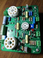
Your board looks nice. Can you post a pic of the other side?
Feedback connectors: See post 86.
Hi ckwong99,
It is funny because you have made solid state amplifiers and you want to try a tube amplifier while I am doing the other way, I have made tube amplifiers and now I am testing a solid state amplifier, only because someone say that the Quasi sound like a tube amplifier Very simple quasi complimentary MOSFET amplifier
I will try to answer your questions :
1) The feedback should be connected to the speaker output of the transformer for a better stability in case of problem, be careful to connect it in the right polarity because it can make an oscillator if unversed, in this case just cross the wire, test at very low volume to avoid a strong sound from the speakers ! Personally I don't use it If you don't use it it can be used for a differential input !
2) See point 1, you can leave it open...
Hi KP93300,
You can leave the FB unconnected for the time being.
I have been running without FB since day one i built it, no oscillation at all.
Good luck !
You can leave the FB unconnected for the time being.
I have been running without FB since day one i built it, no oscillation at all.
Good luck !
Francois,
Yes, I didn't understand your question. I was thinking that you wanted the BOM for the EL84 instead of the EL34 version ! As you know English is not my first language and I do not understand always everything 😕
Hopefully, Vunce answered your question, the jumper was forgotten in the BOM because it was a last minute addition, if you don't use it you can also just make the connection with a wire...
Marc
kp93300,
I didn't use the feedback input from the beginning either 🙂
It is not necessary in UL mode, even when I tested the amplifier in pentode mode it was not needed !
One interesting aspect of this input is that it can be used for differential input mode, with the modification of values indicated on the schema of course.
Rgds,
Marc
Attachments
Your board looks nice. Can you post a pic of the other side?
Attachments
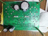
You do some clean work. Thank you for posting your photos
Thank youCarl,
Post 342...
Marc
Marc, your English is great. My French is almost non-existant, except for my ancestoral first name.Francois,
Yes, I didn't understand your question. I was thinking that you wanted the BOM for the EL84 instead of the EL34 version ! As you know English is not my first language and I do not understand always everything 😕
Hopefully, Vunce answered your question, the jumper was forgotten in the BOM because it was a last minute addition, if you don't use it you can also just make the connection with a wire...
Marc
May I encourage you to add the jumper part number to the BOM and reissue it. Else you will keep getting questions about it.
===
Hi kp93300,
Nice work. What is the purpose of having the 10 Ohm 1 w resistors under the board, rather than on top where the heat could escape better? I was thinking of putting all my resistors on top and the film and ‘lytic caps under.
- Home
- Amplifiers
- Tubes / Valves
- EL34 Baby Huey Amplifier