.... What I have done is build a - 95 volt and a +20 volt regulator .... with 450 volts HV and -95, +20 for the bias/driver and el34 outputs I have got 45w at 8 ohms before obvious clipping.
Brian
Brian,
Thanks for your interesting post. Why did you go for -95 v bias. If I remember correctly EL34s need only about -35 V bias for a standing current of 35 ma at 400 V B+. Am I missing something?
Hints on Source Follower Supplies:
The -ve rail for the source follower needs to be sufficent for the follower output (control grid input) to be able to swing negative enough to force to output tube into cut off. The "rule of thumb" for this is 3 times the typical bias voltage. The default Marc EL34 BH is maybe a little lean on negative voltage - but it seems to work OK. Guys wanting to use KT88 or similar (requiring more bias voltage) would want to choose a different power tranny for more negative supply (The specified current source load transistors are rated to 160V).
For the Drain Supply:
For good sound you do not want the Crrs capacitance of the MOSFET to be modulated by the audio signal itself (the audio signal will be present at the Source) So the critcal thing is to have enough Drain to Source Voltage left when the surce is at the positive peak of the audio signal. That peak will usually be at about 0V DC. If you look at MOSFET datasheets you will see that the Crss is fairly constant for Vds (Volts Drain to Source) of +20V or more. So run the Drain at +20 to +30 Volts, more doesn't really improve things any further and just adds to the MOSFET power dissipation - otherwise we would just use the main amp B+ and be done with it.
That was my thinking in the design.
Cheers, Ian
Last edited:
Brian,
Thanks for your interesting post. Why did you go for -95 v bias. If I remember correctly EL34s need only about -35 V bias for a standing current of 35 ma at 400 V B+. Am I missing something?
Ian has just covered the basic issues in his response. In my specific case with 450 B+ I am running -45volts bias at 35ma. In order to drive the tube to 0 volts Vgk and also have a symmetrical waveform at the grid you need to swing from 0volts to -90v, so you need a -95 volt or more supply to do this. I am using a higher than normal transformer primary impedance at 6600 ohms. That means that I need higher voltage swings at lower currents to get the same power output as the typical 4400 ohm transformer. So I plan on running 450volts B+ and with 40ma anode current the bias is about -42 volts. So I am tweeting the driver stage parameters for my particular conditions.
I’ll have more info to follow about 6550 use etc.
Brian
Be careful to stay within the power supply RC filter cap voltage rating on the supply input. I have 330uf 100 volt in there which is why I regulated my supply to -95 which ends up at -93 at the capacitor. I will likely change that cap out to something with a higher rating before I build the amp into a chassis.
Hi pvphil,
I like your built and hope you can clarify some points.
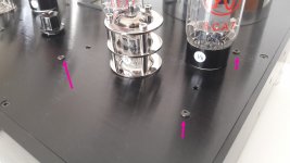
1)Can you share what is the length of the pcb standoff . The standoff hang the pcb off the top plate of the amp.?
2) What is the voltage drop across the 10R for the off board RC filter?
3) I am planning for a wooden chassis and what are the dimensions of your chassis ?
thank you
kp93300
I like your built and hope you can clarify some points.
1)Can you share what is the length of the pcb standoff . The standoff hang the pcb off the top plate of the amp.?
2) What is the voltage drop across the 10R for the off board RC filter?
3) I am planning for a wooden chassis and what are the dimensions of your chassis ?
thank you
kp93300
A little update. I’ve been doing some more testing using 6550 output tubes. The power output levels are similar but the 6550 has a lower output impedance of 3.3 ohms vs 4.3 for the EL34. This is without global feedback. Distortion at low levels (below 5 watts or so was lower with the 6550 but that is likely because of the higher bias current of 60 ma. Distortion was virtually identical at higher power levels.
With my transformer setup I only have an open loop gain of 11 with el34 and slightly lower with 6550. I added some global feedback and did a few measurements. Distortion was cut to about 1/2, gain reduced to 4.6 and output impedance reduced to 1.2 ohms at the 8 ohm tap. Peak power output remained the same at just over 40 watts. Very impressive performance for such a simple 2 stage 3 tube power amplifier.
Next I will test stability and bandwidth.
Very interesting, thanks. Would you mind sharing an explanation of how you added global feedback?
There are 2 terminals labelled feedback on the board. If you look at the schematic you will see that one terminal is ground and the other has a 12k resistor R1 leading to a 470ohm R2 to ground and a 1k R4 into one of the 12ax7 differential pair control grids. What you need to do is connect the 0 ohm secondary tap on the output transformer to the feedback ground connection. Next you need to establish if you have the correct phasing of the output transformer to get negative feedback. If you have a scope this is easy to do. The amplifier input signal should be in phase with the output on the output tap you are going to connect. In my case I had randomly connected the OT with the wrong phase so I needed to invert the connections for each pair of plates and screen grids at the BH board output connector. If you only have an AC volt meter I think you should be able to input 1 volt rms into the amp, measure the output voltage and then measure between the input and output. If the voltages subtract then you are in phase. If they add then out of phase. For example if the amp is outputting 10vrms and the input is 1volt you would measure 9 volts between input and output if they are in phase or 11 volts if they are out of phase. I haven’t tried this method but it seems like it would work.
Once you have the phase correct you can connect the output tap back to the positive feedback terminal. You need to determine the feedback resistor to put in place of the 12k to get the required gain. In my case I used 3.3k. You can use the equation for gain in a non inverting amplifier as a starting point but due to the limited amount of gain available for feedback, in my case ( about 11), the results will be a bit off. In my case the equation would indicate a gain of 1 + 3.3k/470 = 8 but my actual gain was about 4.6
I did not install the feedback capacitor C3 yet. That would be determined by experimentation.
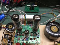
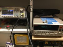
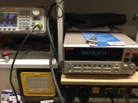
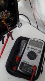
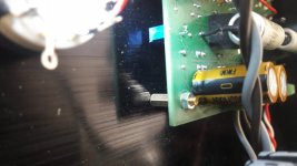
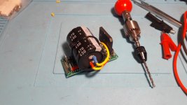
I have shown a picture of the 5 transformer leads connected in the proper polarity for a Toroidy 6600 ohm el34 OT. Also a shot of the amp outputting 10v rms into a 8 ohm load and the third picture shows roughly .5% THD on the Keithley meter.
Cheers
Brian
Once you have the phase correct you can connect the output tap back to the positive feedback terminal. You need to determine the feedback resistor to put in place of the 12k to get the required gain. In my case I used 3.3k. You can use the equation for gain in a non inverting amplifier as a starting point but due to the limited amount of gain available for feedback, in my case ( about 11), the results will be a bit off. In my case the equation would indicate a gain of 1 + 3.3k/470 = 8 but my actual gain was about 4.6
I did not install the feedback capacitor C3 yet. That would be determined by experimentation.
I have shown a picture of the 5 transformer leads connected in the proper polarity for a Toroidy 6600 ohm el34 OT. Also a shot of the amp outputting 10v rms into a 8 ohm load and the third picture shows roughly .5% THD on the Keithley meter.
Cheers
Brian
Attachments
Last edited:
Hello kp9300,Hi pvphil,
I like your built and hope you can clarify some points.
1)Can you share what is the length of the pcb standoff . The standoff hang the pcb off the top plate of the amp.?
2) What is the voltage drop across the 10R for the off board RC filter?
3) I am planning for a wooden chassis and what are the dimensions of your chassis ?
thank you
kp93300

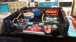
1) The pcb is fixed under the upper plate with small spacer hexagonal column: suleve ™ m3bh1 300pcs m3 entretoise de soutien de colonne hexagonale en laiton male-femelle pour panneau de circuit imprime Vente - Banggood.com
2) The voltage drop across the 10R is about 2 V.
3) The dimensions of my chassis is 376 mm x 308 mm
Regards,

Philippe
Attachments
Last edited:
That is a nice compact size chassis. I am looking at more like 450 x 300 due to all the regulator boards I am using for HV and +- bias voltages.
Yes, 450x300 is better.
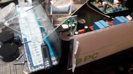
Actually, I build the pre amp in an identical box for a more beautiful set.
I find it a shame not to see the tubes because the box is planned to go under the amp.
So I replaced the aluminum face with a plexigas facade.🙄
After a good test in 2 mm I redo the front in plexi 6 mm.
When it's over, we'll see the preamp tubes running .
.
Good night
Actually, I build the pre amp in an identical box for a more beautiful set.
I find it a shame not to see the tubes because the box is planned to go under the amp.
So I replaced the aluminum face with a plexigas facade.🙄
After a good test in 2 mm I redo the front in plexi 6 mm.
When it's over, we'll see the preamp tubes running
. Good night
Attachments
Phillipe,
Thank you for the information.
Very nice built.
The 2 v across the 10R implies that the total current for the HV of the driver and output tubes is 200ma. this is for a stereo pair of the pcb.
Is my calculation correct ?
regards
Thank you for the information.
Very nice built.
The 2 v across the 10R implies that the total current for the HV of the driver and output tubes is 200ma. this is for a stereo pair of the pcb.
Is my calculation correct ?
regards

Using an xgk6 in place of EL84
I‘m building my Baby Huey to accomdate output 16gk6s tubes. (They are like 16 volt heater 7189) I may also use 7058 tubes for the front end, since they are 13.6 volt heaters and only a few DC volts from the 16gk6 tubes.
I‘m building my Baby Huey to accomdate output 16gk6s tubes. (They are like 16 volt heater 7189) I may also use 7058 tubes for the front end, since they are 13.6 volt heaters and only a few DC volts from the 16gk6 tubes.
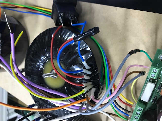
Anyone know how one the Toroidy mains transformers should be wired to the mains, as I can't find a datasheet on their website that shows it? I can see two of the wires have a black sleeve on them, but I would rather not take a potentially expensive guess and end up destroying the transformer (wiring for UK voltage, so wiring the two primaries in series).
Have u took a photo before install your transformer. They dont have a datasheet but each of transformer would stick a label
In Hong Kong 230VAC. I just connected the Red (without black sleeve) to Blue wire (with black sleeve one).
If u still no confident. U can temporarily change thr plug fuse to 1A then switch it on and without anything connect to transformer to get a secondary voltage reading.
In Hong Kong 230VAC. I just connected the Red (without black sleeve) to Blue wire (with black sleeve one).
If u still no confident. U can temporarily change thr plug fuse to 1A then switch it on and without anything connect to transformer to get a secondary voltage reading.
Attachments
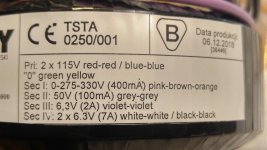
connected the Red (without black sleeve) to Blue wire (with black sleeve one)
Thanks, that it what I guessed it would be, but having made stupid and expensive mistakes with transformers in the past I tend to be a bit cautious now.
For 230Vac main, connect the 2 pair of 110v in series as shown in pic...
An externally hosted image should be here but it was not working when we last tested it.
Last edited:
- Home
- Amplifiers
- Tubes / Valves
- EL34 Baby Huey Amplifier