meanie,
thank you for the info.
i am thinking of housing the BH in a metal case.
Is it better to place all the trimmers on the bottom of the pcb ?
incidentally, I just completed the Marantz 7 clone also. wonderful sound partnered with MOFO !!
thank you for the info.
i am thinking of housing the BH in a metal case.
Is it better to place all the trimmers on the bottom of the pcb ?
incidentally, I just completed the Marantz 7 clone also. wonderful sound partnered with MOFO !!
Hello Marc,
I am interested in the beby huey EL34. I have a Dynaco ST70 that needs rebuilt and was wondering if this would be a good solution. Where can I find the original articles on this design.
Thanks,
Walter
I am interested in the beby huey EL34. I have a Dynaco ST70 that needs rebuilt and was wondering if this would be a good solution. Where can I find the original articles on this design.
Thanks,
Walter
Walter, the design evolved over time so there is no one “original article”. The design evolution is documented in a DiyAudio thread here:
EL84 Amp - Baby Huey
In my opinion the Baby Huey circuit will work well with Dyna St 70 output transformers, and possibly with the power transformer if you comply with the voltages as discussed in this thread. (I don’t remember the voltage and current capability of the bias windings in the Dyna PT. I believe the tube rectifier should be retained since it reduces the B+ voltage to what the Baby Huey EL34 needs) The circuit will have to be built on a custom PCB or breadboard, since the Group Buy PCB will not fit the Dyna chassis, and include the output tubes on the PCB.
Hi meanie, Fabian85 and kp93300,
Thanks you meanie for answering others builders questions 🙂
For TOROIDY output transformer, it is possible to use both 6.6 k and 4 k version, in fact TOROIDY recommend the 6.6 k for the EL34 and the 4 k for the KT88 which is strange because the two tubes are very similar 😕
On my EL34 Baby Huey I have used a Hammond 1650N transformer that I had since a lot of time... It is specified at 4.3 k ! For TOROIDY, I would prefer the 4 k version because we are using a quite low voltage, between 350 and 450 V DC.
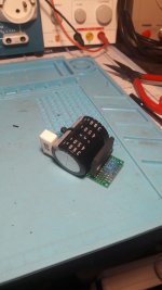
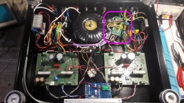
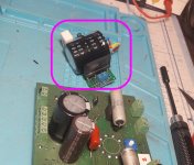
For his EL 34 Baby Huey, pvphil is very happy with the 4 k transformer (see post 238), he has added a very small external circuit for the high voltage (see picture) and has absolutely no hum, ask him 😀
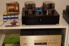
meanie, it seems on your picture that you are using only one 6.3 V heater connection to the DC/DC converter ? I recommend you to use the two 6.3 V 7 A outputs in serial to have 12.6 V AC on your bridge rectifier therefor your DC/DC converter will work in better condition, more efficiently and your bridge will dissipate less because the current will be divided nearly by 2 !
Nice build by the way
Best regards,
Marc
Thanks you meanie for answering others builders questions 🙂
For TOROIDY output transformer, it is possible to use both 6.6 k and 4 k version, in fact TOROIDY recommend the 6.6 k for the EL34 and the 4 k for the KT88 which is strange because the two tubes are very similar 😕
On my EL34 Baby Huey I have used a Hammond 1650N transformer that I had since a lot of time... It is specified at 4.3 k ! For TOROIDY, I would prefer the 4 k version because we are using a quite low voltage, between 350 and 450 V DC.
For his EL 34 Baby Huey, pvphil is very happy with the 4 k transformer (see post 238), he has added a very small external circuit for the high voltage (see picture) and has absolutely no hum, ask him 😀
meanie, it seems on your picture that you are using only one 6.3 V heater connection to the DC/DC converter ? I recommend you to use the two 6.3 V 7 A outputs in serial to have 12.6 V AC on your bridge rectifier therefor your DC/DC converter will work in better condition, more efficiently and your bridge will dissipate less because the current will be divided nearly by 2 !
Nice build by the way
Best regards,
Marc
Attachments

The 2pair of 6.3vac was connected in series before going into the bridge rectifier.
The pic can hardly shows the connected center tap.
The pic can hardly shows the connected center tap.
Good Morning . Seeking clarification
with regard to R5, the 500 R trimmer.
Is this a single turn trimmer?
Is this the same item as listed in the BOM ?
3386P-1-501LF | Bourns 3386P Series Through Hole Trimmer Resistor with Pin Terminations, 500Ω +-10% 1/2W +-100ppm/degC Top Adjust | RS Components
with regard to R5, the 500 R trimmer.
Is this a single turn trimmer?
Is this the same item as listed in the BOM ?
3386P-1-501LF | Bourns 3386P Series Through Hole Trimmer Resistor with Pin Terminations, 500Ω +-10% 1/2W +-100ppm/degC Top Adjust | RS Components
Volume Pot Location & Chassis Question
The new PCB has a 47K resistor, R6 where the volume pot used to be. Where should I wire in a volume pot? I'm sorry if I sound new... I AM!
I have built a phono tube stage before but all the glory is hidden inside the box on that project. Marc did a great service with his PDF of the cutouts but I can't print it to scale and I'm not adding the extra holes for the meter and whatnot. I'm thinking of finding a local metal shop to do the cutouts, I guess I can just bring the PCBs and transformers and let them do the measurements? What have others done on this topic?
OK meanie it is well connected 🙂 For those who didn't see it, I put again the wiring schematic in this message 
YES kp93300 it is single turn trimmer, the reference is in the BOM : 3386P-DF6-501LF Bourns | Mouser France You can put it on the bottom of the PCB (this is what I have done because I have a tube protection on the top)... However for the bias trimmers , I suggest to put them on the top with a small hole to access them 😎
Hi Frankgh, if you are using a volume pot, you can connect the middle point to the input and the bottom point to the GND, the audio input will go to the top connector and the GND to the bottom connector ! In this case you don't need the resistor R6...
Rgds,
Marc
Attachments
What power can I expect ?
Dear all,
I have read the threads since months, and have got two PCBs from Prasi. The only reason why I didn't start yet is because I have an engineer-amp (Pete Millett) and a Tubelab SSE already on the bench and soon finished... but the BH34 is right after them I promise 🙂
What I didn't find in all the threads and documents from Marc is the expected output power at clipping. Plan is to build using my stock of KT77 (EL34), but I haven't purchased anything yet. Did anyone put out some measurements with KT88, EL34, etc ? Please mention yout OPT impedance as well.
Thx to all for the great diy work !
Charles
I have just started experimenting with the BH34 board. I have the 6.6k Toroidy transformers. I had intended to get the 4K kt88 versions but ordered 6.6 by mistake. I have done some initial measurements and found a couple of driver issues when using 6.6k and trying to get higher output powers. With somewhere around 425 volts HV and -85 bias you can get about 30-35 watts. Distortion was quite low open loop at less than 1% until maybe 10v rms and slowly rising with level. Output z was around 4 ohms but I need to do all these measurements again due to my line voltage being quite variable due to living a long way off the main road. I am currently building regulated bias and HV supplies so I can have stable operating conditions for testing. I am using Tungsol EL34 and EH 12ax7. With such a high OT impedance I need to run high voltage and lowish current on the outputs to get good power which means a high - bias voltage. The el34s are biasing at -40 or more, so I am pushing the driver circuitry to the limits. I don’t think I will be able to resist mounting the one test board and all the supplies on a piece of plywood and giving it a listen once I get the bias sorted out.
Good evening, Thank you Marc.😱
Effectively, I had noticed a very very very slight Hum.🙄
The addition of a small RC filter circuit on the HT composed at least (1 rectifier bridge,1 capa 390uF/450V and a R 10 ohms/ 5W) allowed to completely disappear this little hum. 😎
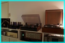
I simply installed this little assembly at the nearest transformer. Now the amp is absolutely and totally silent. It works wonderfully, like here with Oscar Peterson "On Russia" on the Thorens TD 126 mkIII. It's really a great amp, I'm very happy to have realized.
Thanks
Thank you Marc.😱 Effectively, I had noticed a very very very slight Hum.🙄
The addition of a small RC filter circuit on the HT composed at least (1 rectifier bridge,1 capa 390uF/450V and a R 10 ohms/ 5W) allowed to completely disappear this little hum. 😎
I simply installed this little assembly at the nearest transformer. Now the amp is absolutely and totally silent. It works wonderfully, like here with Oscar Peterson "On Russia" on the Thorens TD 126 mkIII. It's really a great amp, I'm very happy to have realized.
Thanks
Attachments
Last edited:
Digital meter/readout
Hi,
dtaylo3 send me the following Private Message :
I don't think this is Private and the answer could interest other builders 🙂 but worse than that : the answer has already been published in post 227 😡
As I have written few post before : READ THE THREAD BEFORE TO ASK A QUESTION WHICH HAS ALREADY BEEN ANSWERED !!!


Thanks for understanding that if you want more support in the futur 😎
Marc
Hi,
dtaylo3 send me the following Private Message :
dtaylo3 said:Where did you get the digital meter for your amplifier? Where in the circuit is it inserted? Looks pretty cool. Very, very nice build!! Most impressive.
I don't think this is Private and the answer could interest other builders 🙂 but worse than that : the answer has already been published in post 227 😡
As I have written few post before : READ THE THREAD BEFORE TO ASK A QUESTION WHICH HAS ALREADY BEEN ANSWERED !!!
Thanks for understanding that if you want more support in the futur 😎
Marc
Hello pvphil,
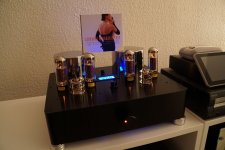
If you are ever interested in my right arm, let me know. But in return, I will need that entire set up of yours😀. The fourth pic, Simply magical!
regards
Prasi
If you are ever interested in my right arm, let me know. But in return, I will need that entire set up of yours😀. The fourth pic, Simply magical!
regards
Prasi
Hi Charles,
As Bfpca wrote, the output power of the EL34 Baby Huey is between 30 to 50 W depending of the power supply and the output transformer... I have not made analysis yet, it is one of my next work when I will learn how to use ARTA or an other of these software to measure power, bandwidth, distortion, noise floor, etc... 🙂
Hi Bfpca,
Don't make a regulated power supply for the bias
The 50 V power supply MUST BE AC ONLY because it is rectified on board to generate the minus 65 V DC for the bias AND the plus 65 V DC for the MOSFET driver ! If you want to make a separate regulated power supply, you will need two : a positive one and a negative one, you should not connect the diodes and bring the two voltages to the two on board capacitors with the right polarity ! To be made ONLY by knowledgeable people
Rgds,
Marc
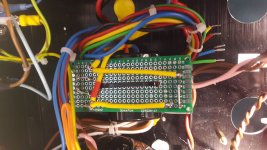
I thought I would show you guys what I’ve done about getting the right spots placed for a top plate
I had two boards copied onto overhead transparency paper basically clear plastic paper
This way I can tape it onto the top plate and do all my cuts. Each sheet in color was under $2.00 at Office Depot
They look better then the pics show them
They can do them in black and white as well
My printer can print these but I was out of the clear paper
I hope this helps you guys with your layout of the case for the amps

Hi Bfpca,
Don't make a regulated power supply for the bias
The 50 V power supply MUST BE AC ONLY because it is rectified on board to generate the minus 65 V DC for the bias AND the plus 65 V DC for the MOSFET driver ! If you want to make a separate regulated power supply, you will need two : a positive one and a negative one, you should not connect the diodes and bring the two voltages to the two on board capacitors with the right polarity ! To be made ONLY by knowledgeable people
Rgds,
Marc
Hi Marc
I have been building tube amps for 20 years and worked for almost 40 in the electronics business. Yes, as you have noted I have built both a + and - regulator. What I have done is build a - 95 volt and a +20 volt regulator and wired them into the BH board at the 270ohm 330uf power filters. I left out the rectifiers entirely. If you regulate the bias you should also regulate HV which I have just finished today. So, with 450 volts HV and -95, +20 for the bias/driver and el34 outputs I have got 45w at 8 ohms before obvious clipping. This is with 35 ma bias and a 6600 ohm Toroidy output trans. Power into 4 ohms on the 8 ohm tap is slightly higher at close to 50w. Output Z is about 4.5 ohms on the 8 ohm tap. Power is slightly lower at 40 ma bias.
You may note that I went to a +20 volt supply for the driver stage. That is more than enough and reduces the power dissipation in the mosfets. The bandwidth with the toroid outputs is an impressive 110khz -3db without any peaking in the response.
These results are without feedback. I would like to try some feedback to reduce output impedance but there is not much headroom in the input stage. Gain open loop in only about 10 at the 8 ohm tap.
I will continue to experiment with bias levels and I am building the second board and starting to plan a chassis layout . The performance of this circuit is quite impressive and I thank you for all of the developement work that has gone into the BH to get it to this point.
PS- I also have some EL84 boards coming which will be easier to build with the much lower drive voltage requirements of the EL84.
Regards
Brian
Hi Carl,
Your post remind me that I have made a plan with the mechanical dimensions based on the CAD layout, I enclose it if it can be useful 🙂
Hi Brian,
Thanks for all these interesting informations and your appreciation of this little amplifier 😎
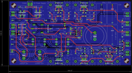
As I have already wrote, I made this PCB to help people, mainly newcomers to tube amplifier, to build easily an amplifier with all components (except transformer of course) on board. In a more sophisticated project I will also use an external board for all power supplies (like I am doing for my futur Quad KT120 still in design, see the power supply layout). You are right with your reduced voltage for the driver, I suggested 50 V AC because it was available from the PS transformer, but -95 V and +20 V make 115 V total, not much less than 2 x 65 V = 130 V 😀
I also add a Front Panel Express file with the implementation of my amplifier to heh you to design your own. The software is available free here : Front Panel Express: Front Panel Design Software and CAD Conversion Service: Home
Best regards,
Marc
Sorry but I cannot load the FPE document even in Zip format, I put a PDF version 😕
Your post remind me that I have made a plan with the mechanical dimensions based on the CAD layout, I enclose it if it can be useful 🙂
Hi Brian,
Thanks for all these interesting informations and your appreciation of this little amplifier 😎
As I have already wrote, I made this PCB to help people, mainly newcomers to tube amplifier, to build easily an amplifier with all components (except transformer of course) on board. In a more sophisticated project I will also use an external board for all power supplies (like I am doing for my futur Quad KT120 still in design, see the power supply layout). You are right with your reduced voltage for the driver, I suggested 50 V AC because it was available from the PS transformer, but -95 V and +20 V make 115 V total, not much less than 2 x 65 V = 130 V 😀
I also add a Front Panel Express file with the implementation of my amplifier to heh you to design your own. The software is available free here : Front Panel Express: Front Panel Design Software and CAD Conversion Service: Home
Best regards,
Marc
Sorry but I cannot load the FPE document even in Zip format, I put a PDF version 😕
Attachments
You are right with your reduced voltage for the driver, I suggested 50 V AC because it was available from the PS transformer, but -95 V and +20 V make 115 V total, not much less than 2 x 65 V = 130 V 😀
Marc
About the +20-95 DC volts. In my case I need -95vdc to get the required grid drive voltage of up to +_45 volts. My operating conditions are not typical so this may not be an issue for other users with more typical output transformers. If I was to use +-95DC I would have 190volts which is more than the voltage rating of the transistors used. You only need enough positive voltage to get the drive voltage up to 0 volts or so unless you want to run grid current in the output stage, so I settled on +20v as a reasonable value.
Brian
- Home
- Amplifiers
- Tubes / Valves
- EL34 Baby Huey Amplifier