JLCPCB black finish does really looks good. Since you mentioned it, I feel free to write the third reason for my choice: black finish is an old trick to cover up beginner mistakes (if any), because you can barely see the traces. ")
I'm still using the point-to-point build of your circuit with octal tubes (post #68). This time I will assemble the noval version because there are more choices for input tubes. I believe that your component value list is good for 6N2P (or 6SL7), but I want to try 12AX7/ ECC83, to increase the gain compared to 6SL7 or 6N2P-EV. Do you already tried 12AX7 and have a suggested value for R1 (first triode anode resistor), R4 (first triode cathode resistor), R7-R8 (phase splitter)?
I'm still using the point-to-point build of your circuit with octal tubes (post #68). This time I will assemble the noval version because there are more choices for input tubes. I believe that your component value list is good for 6N2P (or 6SL7), but I want to try 12AX7/ ECC83, to increase the gain compared to 6SL7 or 6N2P-EV. Do you already tried 12AX7 and have a suggested value for R1 (first triode anode resistor), R4 (first triode cathode resistor), R7-R8 (phase splitter)?
Last edited:
As starting point I will mount the board with the suggested components, without any modification. I believe that there are a few things that can be done to make the component sourcing and placement faster.
The size of the resistors is not the same for all the parts, even if they have the same value. As example, R3 and R8 have the same 100K value but different sizes on the board. I could use 1W resistor for the R8 and 1/4W for R3, obviously: this would make sense on a commercial amplifier, but it seems a unnecessary complication/expense for this DIY board. For Hi-Fi tube amp builds, I use Vishay 1W metal film resistors, and they barely fit on the smaller pads.
Most 47uF 450V capacitors (C6 - C7) have a bigger diameter than the one required on this board. I managed to find a comparatively expensive tall capacitor that fits, but the solution is to allow a bigger diameter, or to specify a lower value. C6 could be bigger, but then there will be interference with the mounting holes and the nearby components.
Pads for input/output connectors are meant to fit the standard small and inexpensive "hobby style" screw terminals that are common on electronics kit and China-sourced boards. I like rugged industrial type removable connectors instead. They allow a quick disconnect of the wiring harness, are rated for high voltages, and they clamp the wires securely. The most common type does not fit well because R4 and R15 are too close. I also don't have the required number of 2 and 3 way terminals of this style on my drawer. I will use a similar but slightly smaller type that can be cut to the required lenght (see picture), but the best approach for me would be to have a 4 way terminal block for the power supply, instead of a separete pwr_in and filament inputs, and a 6-way combined input/feedback terminal block. This could be done by moving the holes a few mm, and will also reduce the total number of cable harnesses to 4, making it easier to disconnect and inspect/modify the board.
Attachments
Do you have a link to a product page for those terminal blocks?
I see what you mean on the sizing for the resistors, and that's a great observation that is very practical. Also, inline power terminal blocks are a great suggestion, and an easy thing to implement, it would make things more tidy for sure. More breathing room around them is a nice idea as well.
What part number capacitors are you using? I'm trying to get an idea on what diameter and lead spacing would be best to focus on for future revisions.
The white cut-to-lenght inline screw type terminals you see on my previous picture is old stock and I can't trace the code yet - I bought a full carton of them years ago for prototype works from a distributor. The standard one is the Phoenix Contact Classic Combicon 5.08mm pitch, with countless copycat imitations. I usually buy the cheaper Wurth or RS components branded one. On the power Combicon series there are many types of terminals, even with a quick-disconnect WAGO style action, but the PCB footprint is always the same.
47uF 450V capacitor (12.5mm diameter, 400mm height): RS components part number 704-7788, Rubycon part number 450KXW47MEFC12.5X40 . I was unable to find a capacitor rated 10000h with this size.
470uF 50V long-life capacitor (12.5mm diameter, 20mm height): RS P/N 224-4404 , Rybycon p/n 50YXF470M12.5X20
0.1uF 760V PP film capacitor: RS P/N 882-9461 Epcos P/N B32912A3104K000 . They are there temporarily, after the first tests I will try replacing them with 0.22uF 630V PET film capacitor RS p/n 755-4535 , Nichicon p/n QXK2J224KTP . I already have a couple of them, and they fit perfectly on the board.
Lingwendil,
I fully understand what it's like to have health concerns. Building tube audio has given a huge positive outlook on life with me. Been fighting rare PAP lung disease for several years.. If it wasn't for audio ideas blasting through my mind and listening to new designs that others said could not be done, tube audio has given excitement for an otherwise difficult life.
Please take care
Thirty years ago, I started building tube audio equipment cutting and trying until success. So, some of us have never had schematics to begin with. We try to help when we can, but life sometimes gets in the way.
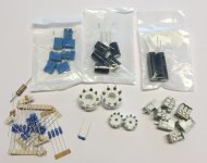
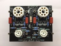
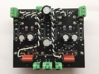
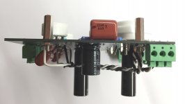
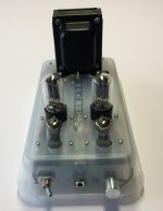
I finished the board assembly, with noval socket heaters wired for ECC83. No mayor issues found, but I had to make a few changes to my original plan to better place the parts. I installed Phoenix Contact PTS series spring PCB terminal blocks: they fit the board almost perfectly, have a strong grip on the wire and a 630V rating. I ended up buying the smaller 0.6W resistors where the board asked for them. I noticed that some resistor pads have a smaller diameter than usual, even for bigger parts such as the cathode resistors. I had to install the small tip on the soldering station, the one I use when I work on microcontroller boards and some SMD parts; it is a bit ackward to use it on tube equipment. It would be useful to enlarge the pads, this will also ease greatly the desoldering effort when a resistor needs to be replaced. I don't like the way C1 is placed across the noval tube socket. The external pads are fine, but they are meant for axial components, while my capacitors have a different shape. The pad right under the tube socket would have been a trap for the cheap 100nF capacitors I was ready to mount (see my previous post), because after the tube socket is soldered in place it would have been impossible to desolder the capacitor without destroying it and maybe damage the board. I ended up installing the 220nF Nichicon capacitors I was saving for later. According to my calculations they are just as good as the suggested 100nF parts on this circuit. I had to put some insulation on the capacitor wire because a tube socket pad is very close to the C1 capacitor pad. I placed R5, C3 and C2 on the component side of the board because the parts fits there perfectly, no need to place them on the other side as suggested by the silkscreen. The hex spacer height is 15mm, exactly the same as the octal sockets, so I mounted the noval sockets 5mm higher than usual. The total height of the noval sockets is now 13mm, almost the same as the octal sockets. This my BOM with RS components part numbers. I used a old 1K 3W carbon composite resistor on R16 position because the new part was not available on time. Tube sockets are sourced from China. The wire for the heaters is 20AWG solid core.
792-3506 - terminal strip, 3 way 5mm
792-3496 - terminal strip, 2 way 5mm
122-4400 - nut, M3
184-2593 - standoff, M3 15mm hex M/F
704-7788 - capacitor, 450V 47uF 12.5x40mm
224-4404 - capacitor, 50V 470uF 12.5x20mm
755-4535 - capacitor, 630V 0.22uF PET
214-1535 - resistor, 1M 1W metal film
214-1456 - resistor, 220k 1W metal film
214-1406 - resistor, 100K 1W metal film
125-1175 - resistor, 1K 1W metal film
683-5887 - resistor, 1K 3W metal film
129-228 - resistor, 1M 0.6W metal film
148-837 - resistor, 27K 0.6W metal film
125-1161 - resistor, 2K7 0.6W metal film
125-1159 - resistor, 1K 0.6W metal film
Edit: I forgot to mention that R3 is missing because I will use a 100K potentiometer at the input. I usually put a capacitor between the volume potentiometer and the amplifier input (R3 would be needed then), but this time I will try a different approach, I will put the decoupling capacitor before the volume potentiometer.
Attachments
Last edited:
Very nice! It's a great looking little board all populated.
I think the goal on the next revision is to bring the caps out from under the sockets and up on top of the board. There should be room if we bring them up to the front of the board. I'm almost thinking that I may remove the larger footprint for axial lead caps, but I know as soon as I do someone will want it there
I'm not sure that I would go without R3, as I think you could get some grid current and maybe some interaction with the grid capacitance at different pot settings? I'm not sure. Probably not a big deal but I'll let others chime in. I'm used to using 100K or so here, and an input cap right at the input RCA, with a 10K pot before that if I run one.
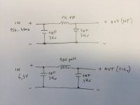
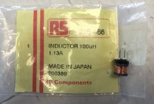
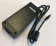
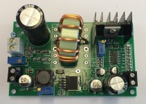
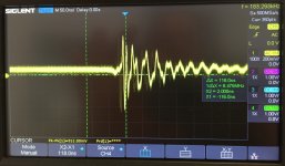
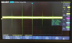
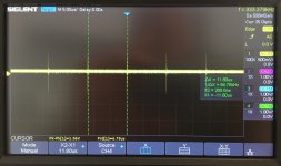
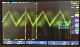
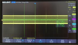
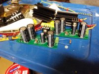
The power supply I will use is the cheap SMPS board from China already mentioned on other forum threads. It is available from several sources: I bought it from eBay - auction ID 173034019336 . This board will allow to change the power supply and tube filament voltage very easily. I will mount the amplifier on a temporary chassis next to this SMPS board, and I will eventually build a traditional power supply after completing tests and tweaks. I bought the SMPS board a while ago out of curiosity but I never tested it. This project is a good opportunity to test my brand new scope. I apologize for the bad screen pictures: I still need to complete the scope setup and then I will get the screenshots directly on a USB stick or network share, but I rather spent my time on the amplifier project. I have chosen this SMPS board because it needs a 12V input to avoid my safety concerns about the insulation from mains supply: this is the duty of the upstream 12V power supply brick. On this tests I used the Mean Well GSM90B12-P1M medical grade power supply (RS components order number 831-9141). It does have full electrical specifications on the datasheet and it bears all the safety marks. It does not need a safety ground, this will avoid ground loops. Many people apparently tested this eBay SMPS board on tube amplifiers with good results, but my first test revealed a big issue. The board does not have any filtering, neither at input and on the outputs. The result is the ugly mess superimposed on the DC outputs you can see on the oscilloscope screen: up to 5Vpp of noise at the 300V output (mostly 80KHz, 320KHz and several harmonics up to several MHz) and a hylarious 1 Vpp of HF noise on the low voltage output. My dummy loads are a car lamp on the filament output and a resistor on the anode supply output. As stop-gap measure I added an empirically designed filter; it surely could be better but I believe is good enough for the next amplifier test. The ceramic capacitors directly soldered on the existing main electrolytic capacitors have cleaned up the HF garbage, and the RC / LC cells greatly dampened most of the fundamental. I also exchanged the original electrolytic capacitors (China branded) with good ones, and this further decreased the noise. The remaining spikes may be something picked up inductively by the scope probe or a ground noise from the Mean Well power supply, but they decay pretty quickly and don't are a concern for me at this time also because I don't plan to use a top quality output transformer. A last remarks: on this SMPS board there is a low value 1W resistor between the negative terminal of the high voltage output and the negative terminal of the input 12V power supply and output low voltage supply. I believe it is a current sense for overload protection. Care should be taken not to short circuit it.
Attachments
-
 filter schematic.JPG64.8 KB · Views: 180
 -
 inductor.JPG45.2 KB · Views: 141
 -
 power supply gsm90b12-p1m.JPG63.6 KB · Views: 212
 -
 smps_board_173034019336.JPG237.7 KB · Views: 201
 -
 Filsupply_filtered_zoom.JPG322 KB · Views: 577
 -
 Filsupply_added_LC_filter.JPG350.4 KB · Views: 583
 -
 HT_with_added_rc_filter.JPG290.7 KB · Views: 599
 -
 FilSupply_factory.JPG408.5 KB · Views: 606
 -
 HT_factory.JPG328.5 KB · Views: 633
I discarded the switched mode power supply board because it cannot supply the required current at 300V; i replaced it with a traditional power supply with CLC filter (4H choke with 240 ohms DCR). The amplifier worked perfectly at the first try with a 15 ohm resistor as load, ECC83 as driver tube and 6H8C as power tube. A quick scope check measures approximately 10Vpp (0.8W) at 1 KHz with clean waveform and a good symmetric clip of the waveform when the amplifier is overdriven. The minimum admissible load on the primary seems to be in the ballpark of 20K. No issues at all with 40K, but less than 20K gives severe distortion at the higher frequencies unless the output power is severely reduced.
I then tried the power and bandwith available at maximum output with several transformers, to select the best one for this circuit. The feedback connection has not been used on this test. 15 ohm load has been connected to the secundary to reflect 20K or more on the primary side. Unfortunately I was unable to find at reasonable prices the cheap Antek AS-05T240 toroidal power transformers specified by Lingwendil, but I tried other types:
- power toroid 15VA 2x6V (RS stock number 671-9053): 22Hz - 6KHz - This is a cheap generic part.
- power toroid 15VA 2x6V (Nuvotem-Talema 91935-P2S2): 22Hz - 7KHz - Good manufacturer, 2x price.
- power toroid 10VA 2x7v (Nuvotem Talema 70040K): 18Hz - 7KHz (recomended on this forum)
- power toroid 25VA 2x7v (RS stock number 124-3873): 20Hz - 8KHz (no-brand but twice the size of the previous one, at the same price tag)
- 70V line transformer OEM29A100: 110Hz - 17KHz (I honestly had better expectations)
- 100VA vintage power transformer (500V CT HT winding = primary, 5V winding = secundary): 50Hz - 12KHz but power output was half of the normal one.
Now the real output transformers:
- Vintage 6V6 PA amplifier (Bogen T260): 30Hz - 19KHz
- Cheap guitar amp transformer (for EL84 PP): 40Hz - 38KHz
- vintage Saba 10W "for ELL80", with gap removed: 15Hz - 24KHz
- big Hi-Fi transformer for EL84PP (price in the 100 euro ballpark): 8Hz - 40KHz
Maximum measured output has been 1.1W.
The vintage Saba transformer is a slightly bigger version of the one I used on my previous build described in this thread. Weight is 600g; size and lamination thickness are the same as Edcor GXSE10. I don't have a GXPP10 to compare, but it may be similar. Saba developed this transformer for ELL80 and some ECL86 radios. It has a paper gap on the lamination, this way it can be used both on PP and SE amplifiers. I removed the paper gap and pressed the lamination in the vice while checking the inductance, then I fastened the laminations with a nylon zip tie. This detail is important while dismantling this transformer. There is a separate feedback winding that I did not use.
The next step will be a test with headphones. The load needs to be 16 ohm or more with the transformers I already have, while my speakers are 6 ohm so I cannot use them. I was hoping to find a suitable toroidal transformer and maybe add a small winding for the speaker, but 7 KHz open loop bandwith will require a excessive amount of global feedback.
Last edited:
I wouldn't mind a pair of those Saba ELL80 transformers, the Saba stuff is pretty nice, and has a great sonic reputation
I've used the 70V line transformers in the past for some builds, and other than the low bass capability, they work well enough and sound pretty good. I was able to get very cheap units to pass 7-10 watts easily with no feedback, within their limitations. Good option for a garage amp or MI use.
Nice work so far! I would be perfectly happy with a 40Hz bottom edge, given the power of the amplifier. Looking forward to seeing how you complete it
I installed the Saba transformers and added a 6.3mm output: this little amplifier does really work well as headphone amp. I like it more than the cathode follower OTL I was using before. It does have more gain and power, and sound is more brilliant. Feedback inputs are still not connected, I will try with feedback later. I had to cancel my original compact chassis build plan because the SMPS power supply did not worked well enough, so I put the amplifier in a temporary clear plastic chassis with same shape, size and layout as the previous point to point octal build. This time I rotated 90 degrees the front and back panels, it seems more practical. The idea was to test the board and then transfer the whole setup on a wooden chassis of the same type as the previous one. Thankfully I made this test on the clear plastic box first because I discovered a flaw on my amplifier chassis layout. I was not obvious on previous tests with speakers. I've gone back to the octal build and it does have the same issue, despite the different power supply: there is magnetic coupling between the power and output transformers. The 90 degrees rotation of the power transformer and 5cm of space aren't enough to avoid a very faint hum while using the amplifier with a low impedence headphone directly connected on the outputs, with feedback disconnected. It becomes virtually unudible to me with the 250 ohm headphone but I know it's there and now I must remove it. After a few checks and moving things around, I confirmed that magnetic coupling is the culprit. I will rebuild the amplifier with output transformers at the front and board in the middle, but maybe I will do something completely different on a bigger square chassis, since the square shape does resonate with the way tubes are placed on this board and a bigger chassis will allow more distance between power and output transformers.
The simplifed input with omitted grid resistor on the board and 100k potentiometer seems to work well. The only issue is that such a large input resistence does pick up some noise when the potentiometer is rotated at the point of maximum resistence. I will try a 47K potentiometer.
I would say that there are no issues with this design when used as headphone amplifier. A provision for two resistors to be used as output attenuator for the headphone jack (next to the feedback input) would be the icing on the cake, but it works very well already. As general purpose speaker amplifier, the output transformer is a show stopper because the most common types cannot be used, and cheap workarounds are a compromise on quality, at least on my tests. Doubling the output tubes would solve the issue, and a noval socket for output tubes would provide more flexibility (ECC82 / 12AU7 / 6CG7 / 6FQ7 ...) with no board size increase.
Attachments
Last edited:
I just saw your pictures of your "engine". Awesome! You should try making a version with 6SN7s or another octal tube. You could call it the "Big Block"Thanks. My next engine will use tubes with top cap. I also have drawn up a 45degree V2 with 813s. Harley music engine.
having seen these mosfets from PeteMillete, i never went back to bipolars,
lots of mosfets that are high voltage and gate zener protected, the 2sk3565 is one such example...
mosfets did not need input currents, just gate voltage and off it works...
Mosfets are so useful with tubes. My current high voltage variety of choice is the IRF820 simply because I have a dozen or so left, I'll be going to the isolated plastic types Pete uses next time I run out and order parts.
Those little PCBs I made for making the ripple filters sure are handy, just put two together last night for the monoblocks I'm working on
Those little PCBs I made for making the ripple filters sure are handy, just put two together last night for the monoblocks I'm working on
Attachments
Is there enough interest in an all noval version of this to warrant a PCB design specifically for it? I'm thinking that a 6N6P or 6DJ8 output stage would be a good way to make transformer selection easier. An option to wire up the input stage as a differential with a tail CCS, and the negative rail could be the DC for the heaters? Might be a good way to go, and should still all fit down to a 100mm square PCB to make it cheap to get made in small quantities.
Alright, started on a user guide. If anything is unclear or you would like me to add anything in particular, let me know! It's hard to think of how to cover all the bases. I'm not covering the power supply details much at this time, but will add info on that when I do more to the PCB I have designed for that.
Attachments
- Home
- Amplifiers
- Tubes / Valves
- 6SN7 push pull flea amplifier project