Fdlima,
1. Some calculations and assumptions:
35V peak to peak = 17.5V peak
165V peak to peak = 82.5V peak
EL34 u = 11
82.5V / 17.5V = EL34 Gain = ~ 4.7
That is about 1/2 x u
It sounds like the EL34 is triode wired. . .
Hello 6A3.
Sorry for taking so long but I have been traveling a lot for work.
I've done new measurements and the results are much better now. I have not changed the circuit so I guess I did measure wrong the output of EL34 last time.
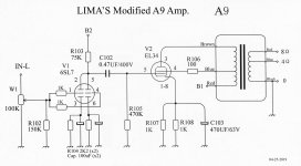
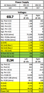
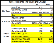
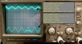
Please see the modified diagram for my A9, the wave form pictures and the voltage table (White cells=measured, yellow cells=calculated), and please double check my calculations below:
New EL34 measurements:
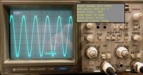
Input (pin 5): 35V peak to peak = 17.5V peak
Output (pin 3): 370V peak to peak = 185V peak
So EL34 gain is 10.6 (which is close to the EL34 specs of u = 11)
Question: The output voltage swing is from 125V to 495V. Is this correct to go up to 495V? This is much above the B1 voltage
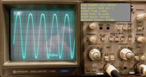
Output of transform (at 8 ohm terminal):
Output: 15.8 peak to peak = 7.9V peak
P = ((V peak) squared) / (R x 2)
P = (7.9V peak squared) / (8 x 2)
P = 3.9 Watts rms
P = 15.6 Watts peak
Question: Is this the expected output power for EL34?
Is the advertised power for this amp is in Wrms or Wpeak?
I don't have a way to measure the transformer primary impedance so I used this formula to calculate it... assuming no loss:
P = ((V peak) squared) / (R x 2)
R = ((V peak) squared) / (P x 2) << Isolating R in this formula:
R = (185V peak squared) / (3.9 x 2)
R = 4,387 Ohms << Does this number seem right to you?
Thanks and I'm looking forward to your comments.
Frank
Attachments
-
 A9 Diagram FL3.jpg295 KB · Views: 502
 -
 Screen Shot 2019-05-05 at 1.21.04 PM.png58.4 KB · Views: 515
 -
 Screen Shot 2019-05-05 at 1.21.54 PM.png42.1 KB · Views: 498
 -
 IMG_6014.jpg83.2 KB · Views: 479
 -
 IMG_6017.jpg80.2 KB · Views: 472
 -
 IMG_6019.jpg99 KB · Views: 80
 -
 IMG_6021.jpg85.3 KB · Views: 76
 -
 IMG_6025.jpg92.1 KB · Views: 100
4W is what you should expect out of a Chinese EL34 amp.
This isn't about cheap Asian-sourced amps/preamps -- but it IS about economics and value") | Page 2 | HiFi Haven
| Page 2 | HiFi Haven
This isn't about cheap Asian-sourced amps/preamps -- but it IS about economics and value
| Page 2 | HiFi HavenFrank,
The EL34 peak plate voltage of 495 is OK. That is when there is very little current in the plate. The plate is rated for up to 800V. In Ultra Linear, the screen voltage increases above B+ by 40% of the increase of the plate voltage. 495V - 185V = 310V. The B+ is near 310V, and 0.4 x 185V = 74V. The peak screen peak voltage is about 310 + 74V = 384V, and the EL34 screen is rated at 450V.
In triode mode (but not the UL you are in), the voltage gain is u x plate load/(plate load + plate resistance). The plate resistance is perhaps 1400 Ohms. 11 x 4,387/(4,387 + 1,400) = 11 4,387/5787 = 8.33 (EL34 gain)
In UL mode, the effective gain is about 2 to 3 x u, and the plate resistance is about 2 to 3 x the triode plate resistance. You got an EL34 gain of 10.6. That seems reasonable.
You are correct in calculating 3.9 Watts rms.
Peak voltage is 1.414 x rms voltage.
Peak current is 1.414 x rms current.
But the peak power is 1.414 x 1.414 times rms power (2 x). That is 7.8 Watts (not 15.6 Watts).
The manufacturer rates the amplifier power according to whatever the marketing group decides to call it. I suspect if you drive the amp very hard into clipping, you might get 15 Watts of extremely distorted power (almost a square wave).
Another way to calculate the output transformer primary impedance is:
185V/7.9V = turns ratio of 23.4.
Impedance ratio is the square of the turns ratio
(23.4)squared = 547.6
547.6 x 8 Ohms = 4,380 Ohms
And this assumes a lossless transformer.
I hope that helps.
pelanj, Is the screeching only in one channel? Are you using negative feedback? What happens if you use a resistive load, and look at the amp output with a scope. Does changing the volume control cause a screech? Does wiggling the input wires cause a screech? How about wiggling the output wires at the amp and at the speaker? Intermittent connection, poor solder joint, wiring dress (placement). Are both the input grids tied together (the model that has parallel triodes).
The other model has an SRPP input stage. Did it always work before, and now this started? How long have you been using the amp? Have you been tube rolling? Are the tube socket connections loose? Is there a schematic on this thread that is exactly like your amp?
I am sorry for the many questions, but there is lots to look for.
Last edited:
Thanks for the suggestions, I will investigate further, this list is a good thing to start with. Mine is factory built model, it should correspond to schematic in post nr. 6 - at least from what I have seen so far. It started doing this one day, but it did not do it yesterday. So it seems more like a cold joint or bad wire or bad contact in a socket.
The EL34 peak plate voltage of 495 is OK. That is when there is very little current in the plate. The plate is rated for up to 800V. In Ultra Linear, the screen voltage increases above B+ by 40% of the increase of the plate voltage. 495V - 185V = 310V. The B+ is near 310V, and 0.4 x 185V = 74V. The peak screen peak voltage is about 310 + 74V = 384V, and the EL34 screen is rated at 450V....
Thank you again 6A3. I always learn new things from you.
Question: Could I get a bit more output power if I replace the Chinese EL34 tubes with a better brand EL34 tubes? Also, my amp is sounding flat, it's missing sound details. I've Googled it found some comments saying the bias could be wrong in the EL34 and recommend increasing the plate current to close the Typical values for the tube. Is this correct? The plate current in my amp is 44mA. Should I increase it to get a better sound? if yes, how much should it be increased?
Thanks,
Frank
The plate current in my amp is 44mA. Should I increase it to get a better sound? if yes, how much should it be increased?
Have you calculated the EL34 plate dissipation (in Watts)?
The plate current in my amp is 44mA.
You sure? That seems quite low for this amp.
jeff
I just installed two new JJ EL34L replacing the Chinese tube and it did improved a little bit but it still is far from the recommended bias of 70% of the maximum limit. Please see the photo with the latest measurements. The plate dissipation is 15.3W which is 61% of the 25W. Feel free to double check my calculations.Have you calculated the EL34 plate dissipation (in Watts)?
Thanks,
FLima
Attachments
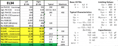
That seemed to be the same result as I have got. When I first built the amp, I almost changed nothing from the schematics(only grounded filament with 100 ohm). I have done extensive measurement and calculation, some of the results are as following:Please see the photo with the latest measurements. The plate dissipation is 15.3W which is 61% of the 25W.
the EL34 Pin 1/8 resistor : Plate current: %plate dissipation :gross AMP power comsuption are as following:
470ohm:46.67ma:60.12%:83.9 watt
435ohm:50.53ma:66.09%:90.2 watt
277ohm:64.70ma:75.9%:101.9 watt
my main purpose of dong this is to find out how it is possible to replace EL34 with KT88, most people 's opinion , after I googled, they think it's necessary to adjust the bias. By my own calculation, without changing the bias resistor value, KT88 will consistently drop 3-4% bias point compared to EL34. in the real world measurement, for example KT88: 435ohm:68.8ma:57.5%:107 watt.
the causes of the theoretical number and real world results , I guess , the tubes quality are different, my stock Shuguang tube, by measuring, Left and right channel bias point can have 4% difference! matched pair Psvane tubes are better, (within 1%). I use u=11 (EL34) and U=8 (for KT88), no doubt in realworld this is not always the case.
my conclusion is, definitely you can safely replace EL34 with KT88 (in the Boyuu kit) I can see most people recommend bias the tube at 90% for class A amp, but lots of people were very happy with 60% and they reckon the sound was the best! I tend to agree with this , bias at around 60% of max plate dissipation for both EL34 and KT88 you will have the satisfactory results! Only concern is the power supply transformer, according to my new kit description, it was supposed be a 200watt transformer. I think it's safe to for my AMP to run a gross 106watt.
Last edited:
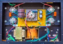
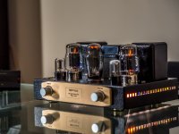
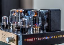
I am very excited after I finished this project. This is the first amplifier I have built since more than 30 years ago.
I guess it must be true love of tube sound. Recently I somehow picked up this old hobby, and realised so much new technologies available! I purchased a class D amp 50watt with bluetooth! it's a DIY kit , but I only needed to put it into the plastic enclousure, I will not claim that was a amp I built. It's so convenient and easy to use, and the sound is loud enough to drive the desktop speakers, but the quality of the sound can't compare with the tube. It's a learning curve, I spent some time in last 3 months to go through Morgan Jones' valve amplifiers, and a lot of online youtube and this forum. This is the great place to learn stuff!
I bought this A9 kit from local ebay seller with surprisingly low price AUD276. I checked and tested everything before starting. Even using low voltage AC to test and estimate the output of the transformer. But what I could not check was the tubes, the 5Z3P turned out to be DOA. I had to wait the longest 2-3 weeks in my life before my order from China arrived. (remember, I am new to tubes and I didn't know i can order a 5U4G locally to save delivery time).
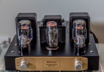
So I probably checked my work dozens of times. Actually, you really can't make any mistakes, after you measured every resistor, capacitor before hand, and each channel you only need to solder 6 resistors and 1 capacitor, what's your excuses to make any mistakes? So I plugged in and hooked it up with a pair of the more disposable speakers. The amp worked straight away, no hum at all. I was glad with this boring result but I am very impressed with the sound after it burned in a bit. Then I worked out to change to KT88/UK , very nice sound! Thanks everyone here for all the advice on this project! It's so therapeutic process for someone at my age.
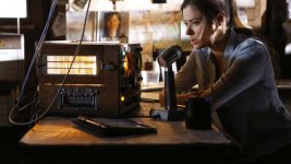
**last picture is from a Netflix TV series/frequency, I like the ham radio with glowing light from inside, so I put this low power, very bright LED strips in side for fun! The TV series itself is good and quite original story to me.
I guess it must be true love of tube sound. Recently I somehow picked up this old hobby, and realised so much new technologies available! I purchased a class D amp 50watt with bluetooth! it's a DIY kit , but I only needed to put it into the plastic enclousure, I will not claim that was a amp I built. It's so convenient and easy to use, and the sound is loud enough to drive the desktop speakers, but the quality of the sound can't compare with the tube. It's a learning curve, I spent some time in last 3 months to go through Morgan Jones' valve amplifiers, and a lot of online youtube and this forum. This is the great place to learn stuff!
I bought this A9 kit from local ebay seller with surprisingly low price AUD276. I checked and tested everything before starting. Even using low voltage AC to test and estimate the output of the transformer. But what I could not check was the tubes, the 5Z3P turned out to be DOA. I had to wait the longest 2-3 weeks in my life before my order from China arrived. (remember, I am new to tubes and I didn't know i can order a 5U4G locally to save delivery time).
So I probably checked my work dozens of times. Actually, you really can't make any mistakes, after you measured every resistor, capacitor before hand, and each channel you only need to solder 6 resistors and 1 capacitor, what's your excuses to make any mistakes? So I plugged in and hooked it up with a pair of the more disposable speakers. The amp worked straight away, no hum at all. I was glad with this boring result but I am very impressed with the sound after it burned in a bit. Then I worked out to change to KT88/UK , very nice sound! Thanks everyone here for all the advice on this project! It's so therapeutic process for someone at my age.
**last picture is from a Netflix TV series/frequency, I like the ham radio with glowing light from inside, so I put this low power, very bright LED strips in side for fun! The TV series itself is good and quite original story to me.
Attachments
I can see most people recommend bias the tube at 90% for class A amp, but lots of people were very happy with 60% and they reckon the sound was the best!
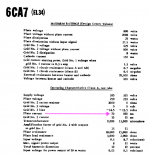
Just for curiosity, what plate current did you end up using for your tube? Because I've seen many posts on the internet recommending 70mA for the EL34 in class A amp, including in the specs in this link http://www.tubezone.net/pdf/6ca7.pdf
Attachments
Thank you Fdlima, for sharing and understanding the joy of achieving this project! The short answer to your question is, I am using the 435 ohm bias resistor (Rc, cathode resistor, the one from EL34 Pin 1 and 8 to ground), when I am using 5z3p rectifier tube, I would get B+ about 338 Volt ( I removed 39 ohm R301), plate current 50.53ma , Cathode current 51.3ma. bias @ 66.09% of max plate dissipation.
When I first built this Amp, everything was same as the schematic shows, (only for convenience Rc=470ohm, not 500ohm), I had the 39 ohm R301 in line to supply B+. So I got B+ 330 volt, R load, which is the DC resistance of the transformer, I measured before started everything, was 204 and 205 ohm for L and R channel. I assume those values will not change (in fact B+ would change all the time! Unexpectedly). I have to do the theoretical calculation here, so ignore it for now and we can change it if we get another real value when circumstances change.
EL 34 , u =11, u is the amplification factor,
-Vg= (0.68* plate voltage)/u
The voltage drop on R load is : 0.07 (70ma, your target plate current) *205ohm=14.35 volt
The plate voltage=330-14.35=315.65 volt, so -Vg=19.51 volt.
Rc (the bias resistor) roughly =-Vg/0.07=278 ohm
I also measured the screen current from pin4/g2 was about 1-2ma, will contribute to Cathode current, so it should be 0.072, some people say the screen current contribute 5% of cathode current, it’s a bit higher than I measured. I don’t take this into consideration anyway.
So now at 70mA , with plate voltage 315v, percentage of bias to the max plate dissipation (25watt) is: 88.38% , this is pretty close to the recommended 90%! You can even increase it to 71.4mA to make it 90%.
Now we can see, the plate current increased from 46mA to 70mA, the Amp total power consumption increased from 83w to 102w(at least), almost 20 watt more, how much change in the sound? I really don’t know, not much, some will say it’s warmer??? I don’t know how to justified the power consumption increased 25%.
When I tested in real time, Rc was 277 ohm, my B+ dropped to 301 volt! –Vg only 18.4 volt, B+ to Pin3 voltage drop was 13.4 volt, so I got bias current 65mA, bias point @ 75%. In the end, I understand the original schematic set at 46mA, and everyone is happy. I would increase a little bit since I had nothing to do and tried to use KT 88 instead.
Thank you Daniellu,
This is very good information.
Using your formula I will play with different values for Rc and check if I get any difference in the sound quality. If I hear any difference in sound, perhaps I'll install a switch so I can easly select between cold and warmer sound.
Cheers,
Flima
This is very good information.
Using your formula I will play with different values for Rc and check if I get any difference in the sound quality. If I hear any difference in sound, perhaps I'll install a switch so I can easly select between cold and warmer sound.
Cheers,
Flima
Unless your Power Mains are very well regulated at the power pole (they are not), And after they come to your house and you put various loads on and off (water heater, dryer, toaster, electric coffee pot, etc.) you will have varying B+ and varying filament voltages.
Also, if you have perfectly regulated voltage at your power mains outlet on the wall, B+ will change if you change the self bias resistor, or if you change output tube types EL34, KT77, etc. Factors: DCR of power transformer primary, DCR of power transformer secondary, dynamic resistance of rectifier tube, DCR of the choke, etc.
Also, if you have perfectly regulated voltage at your power mains outlet on the wall, B+ will change if you change the self bias resistor, or if you change output tube types EL34, KT77, etc. Factors: DCR of power transformer primary, DCR of power transformer secondary, dynamic resistance of rectifier tube, DCR of the choke, etc.
Last edited:
you are right ,precisely! I even thought about taking advantage of the 'instability' of B+. I replaced the rectifier tube with 5U4G, it will increase the B+ by 10 volt. I was thinking about using a solid rectifier to replace the tube, it was said it will increase 20% of voltage. I was concerned about my filter capacitors, they only rated as 450V max, I am not sure if I can do without changing these caps. I think changing of the rectifier tube is one way to make the sound 'warmer'.Also, if you have perfectly regulated voltage at your power mains outlet on the wall, B+ will change if you change the self bias resistor, or if you change output tube types EL34, KT77, etc. Factors: DCR of power transformer primary, DCR of power transformer secondary, dynamic resistance of rectifier tube, DCR of the choke, etc.
as Fdlima mention in previous posts, the sound was flat. but I don't think it's the case in my A9 amp. I am really impressed with the dynamic and soundstage! I don't know if the music source would be an issue. Since I am a new 'audiophile' for last 3-4 months, I only realised in last 3 months that a good DAC is very important. I am using a SMSL SU8, which is a dual ES9038 DAC, it really reproduce the sound very well. For this tube amp, I also tried Wolfson 8740 based DAC, it's warm and clearly separated instruments. That 's when I play Flac or DSD files. I also tried MP3, I would not directly connect my phone or player to the amp, I would bypass the poor DAC build in the phone. So I use bluetooth connection.
My Soundblaster E5 with CS4398 , which is also a classic good DAC, handles the digital signal (without conversion )through bluetooth and converts to analog to feed the tube Amp, I can tell the 320k mp3 files also sound great!. That a few of my thoughts about the quality of music source that can affect our listening experience. unfortunately, in the last 30 year, even I have some so called hifi solid state amp, i was happily being fed with something can be described as 'rubbish in , rubbish out' -
Last edited:
as Fdlima mention in previous posts, the sound was flat. but I don't think it's the case in my A9 amp. I am really impressed with the dynamic and soundstage! I don't know if the music source would be an issue. Since I am a new 'audiophile' for last 3-4 months, I only realised in last 3 months that a good DAC is very important. I am using a SMSL SU8, which is a dual ES9038 DAC, it really reproduce the sound very well. For this tube amp, I also tried Wolfson 8740 based DAC, it's warm and clearly separated instruments. That 's when I play Flac or DSD files. I also tried MP3, I would not directly connect my phone or player to the amp, I would bypass the poor DAC build in the phone. So I use bluetooth connection.
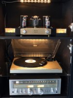
I'm using all analogue equipment so I don't need to worry about DAC quality
. I'm using a Pioneer turntable and a Sansui receiver. Both from the 80's. The receiver has pre-amp out so I leave my tube amp in max volume and I control volume, bass/treble, loudness and inputs through the receiver. It works pretty good.
Attachments
- Home
- Amplifiers
- Tubes / Valves
- Boyuu EL34 A9 Tube Amp