Hmmm... It seems that 5Z4P is indeed a (half!?) directly heated rectifier....
Sorry, I should have said, half indirectly heated.
The 5Z4 and 5Z4GT rectifiers are both Indirectly Heated rectifiers. The cathode works equally with both plates. The 5Z4P looks like a Chinese equivalent to the 5Z4/5Z4GT. The Shuguang data sheet schematic shows 2 cathodes, one for each plate, but both cathodes are connected to pin 8. I believe the drawing with the 2 cathodes, is just a Chinese "clarification" of some US schematics that do not clearly show the 5Z4/5Z4GT cathode equally under both plates.
Last edited:
The Shuguang data sheet schematic shows 2 cathodes, one for each plate, but both cathodes are connected to pin 8.
Yes, I noticed that also. I am considering purchasing a 5R4GY which is a directly heated rectifier with the same pin-out. What's your opinion of this tube?
Directly heated rectifiers warm up quickly, apply B+ earlier. Different rectifiers have different voltage drops, resulting in different B+ voltages. Check rectifier ratings for maximum capacitance of the first cap of a cap input filter. I have not heard a comparison listening test of tube rectifiers. I use solid state diodes, but I do not need the voltage drop of a tube rectifier, and my amplifiers work OK with fairly quick start-up B+. There are lots of factors you have to take into account, and to design for, in order to make that work well.
Hello All. I'm back!!
After about a month of lots of travels, I finally had time to work on my amp again this weekend. And I did a major mod that I wanted to share with you guys.
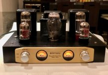
I installed vintage looking VU meters in the front of the amp, and I think it gave a good vintage look to the amp.
I got my VU meter kit for free from Nobsound because they screwed up the delivery of my A9 amp causing delays, but this kit can be bought on eBay.
2PC Panel VU Meter Amplifier DB Level LED Header Display & Driver Board Module 142372810396 | eBay
It does take a lot metal work skills to install these VU meters because you have a make a very clean hole in the aluminum front panel, and also some cuts in chassis front panel but it's worth it.
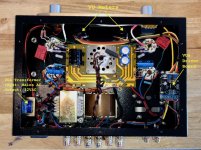
I bought and installed a 12Vac transformer to power the VU driver board because I didn't want to mess with using big resistors to reduce high voltage to 12 volt.
I can give you detailed instructions of how I installed these VU meters if you're interested.
Cheers.
Flima
After about a month of lots of travels, I finally had time to work on my amp again this weekend. And I did a major mod that I wanted to share with you guys.
I installed vintage looking VU meters in the front of the amp, and I think it gave a good vintage look to the amp.
I got my VU meter kit for free from Nobsound because they screwed up the delivery of my A9 amp causing delays, but this kit can be bought on eBay.
2PC Panel VU Meter Amplifier DB Level LED Header Display & Driver Board Module 142372810396 | eBay
It does take a lot metal work skills to install these VU meters because you have a make a very clean hole in the aluminum front panel, and also some cuts in chassis front panel but it's worth it.
I bought and installed a 12Vac transformer to power the VU driver board because I didn't want to mess with using big resistors to reduce high voltage to 12 volt.
I can give you detailed instructions of how I installed these VU meters if you're interested.
Cheers.
Flima
Attachments

Well done!
Gorgeous looking amp.
I notice that you are taking B+ from the correct pin of the rectifier. I will make that correction on my A9
Gorgeous looking amp.
I notice that you are taking B+ from the correct pin of the rectifier. I will make that correction on my A9
I fried my power transformer.
Hello ... I've just assembled one of these kits. It worked really well for over 20 hours, but had too much mains-frequency hum. After some simple modifications, it worked about 4 hours, but then failed, with the power transistor insulation melted and running out of the bottom.
It could be concidence, but it seems reasonable to suspect my recent meddling: what I did was
1) added resistors to ground the heater circuits, which stopped the hum. Win.
2) added cathode bias resistor bypass capacitors, which improved clarity. Win.
3) about 4 hours later: no sound; acrid burning smell and smoke wisps; all heaters not lit up any more; fuse blown; all transformer pairs short circuit.
More troubleshooting tomorrow, but I suspect one of the bypass capacitors went closed-circuit.
But I'll definitely need a new power transformer 🙁
Can you post a few more details (and good pictures)?I fried my power transformer.....................
More troubleshooting tomorrow, but I suspect one of the bypass capacitors went closed-circuit.
How did you add the heater resistors, and what value were they?
Which cathode resistors did you bypass with caps?
The transformer failure could be coincidence, but likely not, as you have inferred. It could have been a defective transformer.
You could always try contacting the vendor about a (warranty) replacement, but not if you are sure that it was your mods that caused the failure.
You can find the same power transformer on aliexpress, or source a different brand.
All part of the 'fun' of DIY!🙂
This thread is great. I bought the A9 built and with Lowthers, the line induced buzz was unbearable. I balanced the heaters with two 1k resistors since I had none more suitable at hand. I can still hear some hum/buzz, but now I can actually listen to some music. For the money, the amp is awesome. It is quite easy to do some tuning inside, plenty of space. I will maybe add filtering capacity to make it fully silent and some of the mods described here.
Is it worth balancing the power tube heaters as well? I found some chassis mount hum pot, which might be worth installing.
pelanj,
I believe that most or all of the output stages in this thread use cathode bypass capacitors to ground.
But as a common practice, I always use a pair of resistors as a pseudo center tap to ground the filament secondary, if there is no actual center tap that I can ground (I never like to just let things 'float').
A Quality output tube should not exhibit hum effects due to filament to cathode leakage, especially of the cathode has a bypass cap to ground. I would expect that to be a very small amount of hum compared to all the other causes of hum:
Putting the B+ choke under one output transformer. Orientation of the laminations of power transformer and B+ choke, versus output transformer laminations. Ground loops. Design of the B+ circuit and values (B+ ripple). Improper grounding or not grounding of inputs. Unbypassed input stage cathodes, or if they need to be unbypassed, proper selection of Quality tubes. Wiring practices, twisted pairs of AC wires, placement (like near to a grid circuit and parts), etc.
Peel the outside layers (larger hum) off the onion, before you attack the center of the onion.
The 50 Hz hum is low enough not to bother me at the listening place, it is more the residue of the 50hz harmonics, that almost went away when it added resistors to ground on the heaters of the preamp tubes. I think I will just add them also to the power tubes, that should not hurt anything.
My second guess is filtering, so I will add some capacity behind the choke.
My second guess is filtering, so I will add some capacity behind the choke.
Did *I* really fry the power transformer...?
Standard mods from this thread:
Two 100R resistors in series across the two heater feeds, with the centre 'tap' at chassis ground. Also, a 470uF cap across R104 and R204. (The EL34 already has this cap in place.)
Testing just now: the resistance across the heater feeds is 50 ohms - consistent with the power transformer being closed-circuit. The resistance across the cathode RC cct is 2k, as it should be. So, the added components are what they should be ... no confirmation (yet) that I actually broke it.
I'll start unsoldering bits soon, so I can check components without local circuitry getting in the way.
Indeed. I'm learning more because of this, and having more fun 🙂
Cheers.
Can you post a few more details?
Standard mods from this thread:
Two 100R resistors in series across the two heater feeds, with the centre 'tap' at chassis ground. Also, a 470uF cap across R104 and R204. (The EL34 already has this cap in place.)
Testing just now: the resistance across the heater feeds is 50 ohms - consistent with the power transformer being closed-circuit. The resistance across the cathode RC cct is 2k, as it should be. So, the added components are what they should be ... no confirmation (yet) that I actually broke it.
I'll start unsoldering bits soon, so I can check components without local circuitry getting in the way.
All part of the 'fun' of DIY!🙂
Indeed. I'm learning more because of this, and having more fun 🙂
Cheers.
Attachments
No, I've said that wrong - I mean the resistance from one of the heater supply leads to ground is 50 ohm.... the resistance across the heater feeds is 50 ohms ...
The 6.3V transformer filament winding DC resistance is far less than 1 Ohm. Put a 100 Ohm resistor on one lead to ground, and another 100 Ohm resistor from the other lead to ground. That makes either lead of the winding to ground 50 Ohms, right?
And the resistors present 200 Ohms across the transformer filament winding is in parallel with the sub-ohm DC resistance of the winding.
By the way, 300mA of 12A_7 or similar tube is 21 Ohms when the filament is warm (a lot less when it is cold at start up).
And the resistors present 200 Ohms across the transformer filament winding is in parallel with the sub-ohm DC resistance of the winding.
By the way, 300mA of 12A_7 or similar tube is 21 Ohms when the filament is warm (a lot less when it is cold at start up).
Last edited:
The 6.3V transformer filament winding DC resistance is far less than 1 Ohm.
Hmm. I did not know that. Thank you.
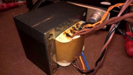
So I don't really know the condition of the transformer other than looks and smell as though it got really hot. (Pic attached.)
I've since discovered the power switch is broken (just keeps turning with no stops or on/off click.)
So I have (i) faulty power switch, (ii) blown fuse, (iii) burnt transformer. I'm trying to think of scenarios for what order that could happen - which caused which - or whether someting else 'down the line' is the cause.
Attachments
DavidN,
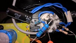
1. What is that 470uf 63V cap connected to?
2. You have a 400V orange coupling cap. What is the highest B+ voltage at turn on before the tubes warm up. Is it possibly more than 400V B+?
I always use a 600V coupling cap because I use solid state rectifiers, and my B+ rises to about 465V before the tubes warm up. Even with many types of tube rectifiers, the rectifier warms up before the input and output tubes, and the B+ can easily exceed 400V.
Example of what could happen to a coupling cap:
My driver plate load resistor drives the coupling cap, which drives the output tube grid resistor. The current is limited by those two resistors, but the voltage is not limited to less than the turn-on B+ of 465V.
If your coupling cap shorts, the output tubes will draw excess current, and perhaps cause the output tube bypass caps to short, and even if not, the excess current on the B+ may take out the power transformer, output transformer, etc.
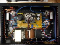
1. What is that 470uf 63V cap connected to?
Sorry the picture doesn't show clearly: they're radial capacitors bridging the cathode resistor, from ground to pins 4 and 7. (Pic 1)
2. ...400V orange coupling cap...
The coupling capacitors are the ones supplied in the kit. I can't test any voltages before I replace the power transformer.
The chassis currently has no PT, and I've removed the valves. Testing continuity/resistance indicates neither coupling caps nor bypass caps are shorting.
Thanks for you insight. I'll revisit the voltages when I have a PT that doesn't pop the fuse. (By 'pop', I mean 'vaporise the wire so fast that the glass sleeve shatters'.)
Attachments

Often when people design an amp, they look at what the voltages are across the capacitors when the amp is warmed up and operating. They forget about the higher voltages there are when the amp is just turned on, and during the time until the amp is warm.
That goes for coupling caps and B+ caps.
A shorted B+ cap can take out a power transformer, fuse, rectifier, etc, all or just some of them.
A shorted rectifier can take out a power transformer, fuse, and the B+ cap, all or just some of them.
A shorted output tube can take out a power transformer, fuse, output transformer, self bias resistor, bypass cap, etc. or just some of them.
A gassy output tube, but that is not shorted, can take out a power transformer, fuse, output transformer, self bias resistor, bypass cap, etc. or just some of them.
Measure from the control grid of your output tubes to ground, they should measure the same as the grid resistor (470k Ohms?). if the grid resistor opens up, or there is a bad connection, the grid can float, and the output tube draw excessive current, causing other things to burn out as listed above.
Last edited:
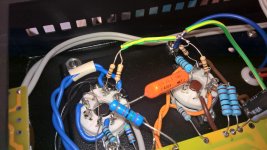
Any builder of that amp, should check to see if the specific rectifier that is installed is an Indirectly heated model (has a real cathode, not just a filament).
The indirectly heated cathode connection is usually on pin 8.
For an indirectly heated rectifier, if you connect R301 to pin 2, that would make the cathode current have to travel through the filament.
For example, 2 amps of the 5V filament winding through the filament, plus another 1/2 amp of peak cathode current all going through the 5V filament on its way to R301 and the B+ filter.
Therefore, the correct connection of R301 would be to pin 8.
I just corrected my amplifier, thanks again, 6A3sUMMER, for pointing this out.
Attachments
- Home
- Amplifiers
- Tubes / Valves
- Boyuu EL34 A9 Tube Amp