VictoriaGuy,
This thread has 900 posts. There have been several schematics, not all the same. I believe some in this thread have built their own amp, with various parts, just referring to the schematic (parts may or may not be the same). Others purchase the kit. But I believe there are at least 2 versions of the kit.
Fdlima has one version of the Boyuu amp. Is there more than one version? Were there any parts changes during the production run(s) of the Boyuu amp? How about any circuit changes of the Boyuu amp?
Getting different results only takes: One part change (self bias resistor, output transformer, tube rolling, UL tap was 40% but now is 50% etc.). Output mode change (UL, Triode, Pentode), Addition of negative feedback (and method: output tap to output tube cathode, output tap to driver cathode circuit, Schade feedback, etc.).
Most of these kit amps seem to have a circuit board; but that does not stop eager builders from making major changes.
And then there are tubes, weak tubes, tube ‘substitutes’ and Bogus tubes.
Apparently, some do get low power from (some versions of) these amplifiers.
For any amplifier that is not performing as the owner expects, there are lots of specifics that need to be known by anyone that would attempt to troubleshoot it via the internet.
I do not always write clearly. I also make mistakes. I said: “It sounds like the EL34 is triode wired.” Of course I can not “hear” what his amp sounds like. I should have said: “Perhaps you wired your amp in triode mode.”
My next post will address something about long threads.
Thanks to all on this forum who read, write, build, listen, and participate.
To the Moderators of this Forum:
I believe the rules state that we need to do a search before we start a new thread. That has several advantages: It reduces the amount of threads that come up in a search (easier to find what you want). It allows the many contributions on a subject or device, etc. to be in one place (one thread). I am sure many others can list other examples of advantages.
But there is another side as to whether or not to start a new thread:
Using this thread as an example (unless someone else puts up a post before I finish my edits, this will be post # 902).
My post 901 shows that unless you read through all the previous 900 posts, you may miss something. We do not all have the time to read through 900, and analyze each post, and then give help based on all of that to a new (late) “poster” who is having problems. And did that new poster read through all 900 posts so that we are all on the same page, so to speak.
And a late post may refer to a schematic, but which one? And is there a modification that is not in the schematic?
Starting with a new thread might make the person who starts that thread to be careful to give details, so we can start from there; instead of starting with some assumptions about posts 400 to 450 that similarly address the problem.
No, I do not really propose making it easier to start a new thread, but I am sure some get frustrated by not having a new one on a clean slate.
Does anybody have a solution?
Thanks. It wasn't a big problem.
Around 'here' I see my small role as answering some of the very easiest questions, to free up the time of people like you to take care of the 'higher level' topics.
I'm sure it must be a bit tedious for experts to answer the same basic questions year after year, but it does help to engage beginners in the hobby.
Little bit of help please
Dear all, First of all I will like to say that I appreciate all the work you put in this . Based on what I saw here I decided to buy myself this kit Boyuu A9. I was very excited when it arrived and I started the assembly and here is the point where the problems started. After assembly at first power on I have a huge HMMMMMM in both speakers. After reading the posts form here I could not fix it. I tried also the moods from VictoriaGuy but this also didn`t help. The only improvement was obtained when I put the 200 Ohms 3w resistors in parallel with C302. The HMMMMM was gone but the R301 started to get very hot ( it was so hot that started to smoke ). Any ideas are most welcome.
Thank you.
The only improvement was obtained when I put the 200 Ohms 3w resistors in parallel with C302. The HMMMMM was gone but the R301 started to get very hot ( it was so hot that started to smoke ).
Any ideas are most welcome.
Hi!
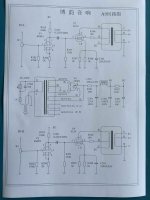
Please see the schematic below...is this the one you are using?
I'm not sure exactly what you did (or why) but...
Putting a 100R or 200R resistor from the B+ high voltage rail to ground (bypassing C302) is definitely NOT a good idea. Some Ohms law and power calculations will show that..
So definitely remove that 'mod' as a first step.
Then, double-check your wiring against the schematic.
Next step for me would be to remove all the tubes (and the speaker), power up the amplifier and check for the right heater/filament voltages at the correct pins on the tube sockets. Use the AC volts setting on your meter.
You do know that the tube pins are numbered clockwise, looking at the bottom of the tube? -i.e. from the inside of the chassis- this is a quite common beginner mistake.
Report back with the heater voltages and pin#s, and post some pictures of your wiring, and somebody here will help.
Attachments
Last edited:
After assembly at first power on I have a huge HMMMMMM in both speakers.
Hi Marius,
Welcome to the group. This group has helped me a lot and I have learned a lot from them too.
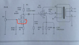
I had the same huge hum on both speakers when I first powered on my A9 amp and the problem was that pin 4 of the pre-amp tube needs to connected to pin 1. this connection is not shown in the diagram that comes with the kit. The loud hum should go away once you connect pin 4 with pin 1.
Let me know if this fixes the problem.
Frank
Attachments
Greetings Forum Family, I want to say thanks for a great read on this amplifier, it served as a very informative preamble. I purchased the kit on Ebay and assembled it incorporating a few mods that I gleaned from here including some component changes. The amp has been in use for the past 6 weeks with no issues.
It sounds wonderful playing a variety of program material through Klipsch RP-160M loudspeakers!
It sounds wonderful playing a variety of program material through Klipsch RP-160M loudspeakers!
The amp has been in use for the past 6 weeks with no issues.

Good work!
Hi VictoriaGuy,
Thank you for your posts here and also for your professional approach.
Hi Fdlima,
You are a life saver. Thanks to your help I finished my project and I can enjoy listening and thanks to the moods that I found here the sound is brilliant . Next project will be a RIAA pre amp. Any suggestions ?
Thank you again for your help and support
Marius

Frank:
Good work in zeroing in on the problem Marius was having! (Experience counts!)
I agree on the schematic needing improvement. The connected grids are 'obvious' to most experienced builders (plates in parallel, cathodes in parallel, etc..) BUT many buyers of the Boyuu and similar kits are not experienced, so no details should be omitted from the schematic.
Marius: You are lucky; that was quite quick troubleshooting and cure!
Eli Duttmann's phono preamp voltages
Good work in zeroing in on the problem Marius was having! (Experience counts!)
I agree on the schematic needing improvement. The connected grids are 'obvious' to most experienced builders (plates in parallel, cathodes in parallel, etc..) BUT many buyers of the Boyuu and similar kits are not experienced, so no details should be omitted from the schematic.
Marius: You are lucky; that was quite quick troubleshooting and cure!
You have probably already found this thread:Next project will be a RIAA pre amp.
Any suggestions ?
Eli Duttmann's phono preamp voltages
Hello,
I've bought a DYI Boyuu EL34 A9 amplifier. As said by some users already, it comes with just electrical diagram and that's all, but I've managed to build it. I have experience in electronics but this is my first ever tube amplifier. The supply works OK when I turn it on, but I just get a huge hum from the audio output, despite having added balancing resistors across the heaters of both the EL34 and 6N9P. When I switch it off, until the capacitors discharge, the audio comes out nicely for a few seconds, until it fades. Please does anybody have some suggestions? Thank you.
I've bought a DYI Boyuu EL34 A9 amplifier. As said by some users already, it comes with just electrical diagram and that's all, but I've managed to build it. I have experience in electronics but this is my first ever tube amplifier. The supply works OK when I turn it on, but I just get a huge hum from the audio output, despite having added balancing resistors across the heaters of both the EL34 and 6N9P. When I switch it off, until the capacitors discharge, the audio comes out nicely for a few seconds, until it fades. Please does anybody have some suggestions? Thank you.
Guilio Villani,
Is the input tube in parallel mode, (cathodes tied together, and plates tied together, like in post # 10)? If they are tied together, the grids also need to be tied together (some schematics do not show the grids tied together, but in this mode, they need to be tied together).
Is the hum more from one channel, or roughly equal in the two channels? Try swapping the input tubes to the other channel. Try swapping the output tubes to the other channel. does the hum move from one channel to the other channel?
How much hum? ( DMM AC measurement)
Or are the input tubes in in SRPP mode? (stacked in series like schematic in post #3).
Find a schematic in this thread that exactly matches your amp.
Tell us what is that post #. This thread is Very long, and the answer may be in there (several times), but it is easier to answer correctly if you answer the questions above, and find the correct schematic too.
Last edited:
Hello 6A3sUMMER,
thank you very much for the suggestion. Indeed I should have realised that with the cathodes and plates tied together the grids should also be. Connecting pin 4 and 1 of 6N9P together drastically reduced the hum. The correct schematic that matches my amp is shown in post 908. The amp now works fine, I left it run for 2 hours full volume with no issues. Great! I did notice though that there is residual hum when the volume is halfway and it completely disappears when the volume knob is full way, i.e. input straight to the grid or fully grounded. Also the hum increases a bit when I touch the volume knob. I used a shielded cable from the inputs to the potentiometer, with the shield grounded at BOTH ends, i.e. at the inputs PCB, which is then connected to the ground of the main PCB, and at the volume potentiometer side. Maybe I need just one ground connection, to avoid ground loop? The chassis of the amp is earthed but the amplifier ground is floating with respect to earth. All the heaters and power cables are twisted and I tried to keep them distant from high impedance lines, to the best of my (still very limited) expertise in building tube amps.
thank you very much for the suggestion. Indeed I should have realised that with the cathodes and plates tied together the grids should also be. Connecting pin 4 and 1 of 6N9P together drastically reduced the hum. The correct schematic that matches my amp is shown in post 908. The amp now works fine, I left it run for 2 hours full volume with no issues. Great! I did notice though that there is residual hum when the volume is halfway and it completely disappears when the volume knob is full way, i.e. input straight to the grid or fully grounded. Also the hum increases a bit when I touch the volume knob. I used a shielded cable from the inputs to the potentiometer, with the shield grounded at BOTH ends, i.e. at the inputs PCB, which is then connected to the ground of the main PCB, and at the volume potentiometer side. Maybe I need just one ground connection, to avoid ground loop? The chassis of the amp is earthed but the amplifier ground is floating with respect to earth. All the heaters and power cables are twisted and I tried to keep them distant from high impedance lines, to the best of my (still very limited) expertise in building tube amps.
Guilio Villani,
Is the hum 50Hz, 100Hz, or what?
Broadband noise?
Oscillation?
50 Hz is caused by mains.
100 Hz is caused by full wave B+ rectification.
I believe the B+ choke (100Hz) is under one of the output transformers, there can be magnetic coupling.
I am not sure of what you mean by:
"The chassis of the amp is earthed but the amplifier ground is floating with respect to earth."
. . . chassis is earthed . . . do you mean the ground of a 3 wire power mains is connected to the chassis?
If not, try grounding the power ground to the chassis.
. . . the amplifier ground is floating with respect to earth . . . does that mean that all the grounds I see in the schematic are not connected to the chassis, or power mains ground, or both?
Do be careful, different countries have different power mains, different ways that your amp and other equipment is grounded, or is not grounded, etc.
Last edited:
Hi 6A3sUMMER ,
thanks, I still do not know whether the hum is 50 or 100 Hz, going to check with a scope.
That's correct, the ground of the 3 wire power mains is connected to the chassis, and the ground of the schematic is not connected to it. Also I have grounded the shielded cable bringing the signal input at two points, and I am not sure it is a good idea. I am going to try and come back to you.
Hi 6A3sUMMER ,
thanks, I still do not know whether the hum is 50 or 100 Hz, going to check with a scope.
That's correct, the ground of the 3 wire power mains is connected to the chassis, and the ground of the schematic is not connected to it. Also I have grounded the shielded cable bringing the signal input at two points, and I am not sure it is a good idea. I am going to try and come back to you.
Hi Giulio, I built one of these amps recently, it is very quiet even through very efficient loudspeakers. Connect the schematic ground to the chassis ground. That will reduce the hum significantly.
I have some photos of my amp's internal wiring. I will upload them here as soon as I work out how to.
- Home
- Amplifiers
- Tubes / Valves
- Boyuu EL34 A9 Tube Amp