For those who grounded the heater wires via resistors. To prevent hum.
Did you guys do it for both power and preamp tubes?
That question only applies when there are multiple heater windings without center taps (as in the Boyuu), so there's probably not a general rule on it.
Also, the center tap (or 'equivalent' via resistors, or 'hum pot') doesn't necessarily connect to circuit ground.
I'd probably focus on the preamp heaters first. Signal/Noise ratio concerns would point there for me. But there's no harm in doing the power tube heaters, as far as I can see.
I've seen designs where the preamp tubes were DC heated to reduce hum with AC heating on the power tubes.
Do you hear hum from your amp output (at speakers) with the inputs shorted?
I was going to ground the resistors to the chassis.
I'll start with the preamp heater.
Right now I have both heaters grounded to the circuit board without any resistor. Just a wire. It's pretty quiet this way.
I'm curious if I create an artificial centre tap. What effect it would have. Could it affect the tone of the amp?
I'll start with the preamp heater.
Right now I have both heaters grounded to the circuit board without any resistor. Just a wire. It's pretty quiet this way.
I'm curious if I create an artificial centre tap. What effect it would have. Could it affect the tone of the amp?
I was going to ground the resistors to the chassis.
I'll start with the preamp heater.
Right now I have both heaters grounded to the circuit board without any resistor. Just a wire. It's pretty quiet this way.
I'm curious if I create an artificial centre tap. What effect it would have. Could it affect the tone of the amp?
I'm not clear on exactly what you are saying.
I would be careful how you connect the circuit 'grounds' to the chassis - there was a lot of discussion a few pages back in this thread about that...and Wavebourn posted an update a couple of days ago.
How do you have the heaters grounded to the circuit board now? One side connected to circuit ground? What point in the circuit ground have you used for connection?
The resistors (100 ohm) connected to the two sides of the heater wiring are the 'artificial centre tap'. It won't affect the 'tone' but can help with hum reduction if done properly. Or it can make things worse....
")
If you could make a quick sketch of your plan and post it here, it would help.
EDIT:
I looked back to Post # 458-459 and saw you had mentioned this before. Re-posting some of that info and also what you read from the Merlin site (and others) would help to understand where you are at in your thinking now.
If you don't have any hum at the speakers, I wouldn't worry too much about changing anything. There are other things that can be done (like better heater wiring twisting, etc) but it's not easy at this point and I wouldn't bother unless there is a hum problem with the inputs shorted.
Last edited:
In post 458. You can see how I've grounded the heaters. Since then I have wound the heater wires tighter. I'll take a picture and post later on.
My A9 sounds pretty good. There's an openness to it. However when I turn it up I find it harsh. So I'm looking for ways to reduce the harshness.
My A9 sounds pretty good. There's an openness to it. However when I turn it up I find it harsh. So I'm looking for ways to reduce the harshness.
I looked at that picture, and I can't see how you've done it, actually. Our build wiring always looks very clear to us, not so much to others!In post 458. You can see how I've grounded the heaters.
Good!Since then I have wound the heater wires tighter. I'll take a picture and post later on.
Without a scope and audio generator, it will probably be difficult to diagnose this at a distance.My A9 sounds pretty good. There's an openness to it. However when I turn it up I find it harsh. So I'm looking for ways to reduce the harshness.
Audio generators or test tones are easy from computer or CD - perhaps you could post mp3 files, though getting good fidelity via computer or phone microphones isn't always easy.
Sometimes reports of sound quality problems are referring to very subtle ('golden ears department') things, sometimes really awful distortions that the builder is trying hard to overlook. It's tough to tell without data.
First step for me is always a very careful check of the wiring - amps can work even with wiring mistakes.
Next would be tube checks. Easier if the problem is only in one channel.
Grounding one side of the AC heater wiring was pretty common in the 50s and 60s - I've seen it in a lot of older console hi fi units. Often they just bent the lug on the tube socket down and soldered it to the chassis.
That doesn't seem to be done so much nowadays - perhaps we have lower tolerance for hum now that we aren't listening to lo-fi record players as sources?
That doesn't seem to be done so much nowadays - perhaps we have lower tolerance for hum now that we aren't listening to lo-fi record players as sources?
Post 611. Also shows the grounded heater wires. Perhaps it is more clear.I looked at that picture, and I can't see how you've done it, actually. Our build wiring always looks very clear to us, not so much to others!
I will double check everything. If also tried other tubes, with some improvements. I'm trying to get my hands on an osiliscope. I'm thinking that this is just the way the amp sounds to my ears.Without a scope and audio generator, it will probably be difficult to diagnose this at a distance.
Audio generators or test tones are easy from computer or CD - perhaps you could post mp3 files, though getting good fidelity via computer or phone microphones isn't always easy.
Sometimes reports of sound quality problems are referring to very subtle ('golden ears department') things, sometimes really awful distortions that the builder is trying hard to overlook. It's tough to tell without data.
First step for me is always a very careful check of the wiring - amps can work even with wiring mistakes.
Next would be tube checks. Easier if the problem is only in one channel.
Depending on where you live, you may be able to get a decent used analog scope for not too much money. Try to get some decent probes with it. The digital scopes have gotten into the 'reasonable' price range lately as well. New ones aren't much more than people are asking for used ones, around here. Still, it's a lot of money unless the hobby has grabbed you.I'm trying to get my hands on an oscilloscope.
Possibly that's true. I built a very similar Chinese amp and it sounds good to me, with my aging ('older') ears, my music, my sources, and my speakers. Lots of variables there!I'm thinking that this is just the way the amp sounds to my ears.
What different tubes have you tried?
Hello All,
Firstly, Congratulations! This is a great forum for A9 amplifier. I'm glad I found it.
I ordered the A9 Kit from Amazon and I'm really looking forward to it to arrive so I can put it together. I am very experienced with electronics (I've repaired consumer and professional audio system for over two decades) but I don't have experience with tube amplifiers except for swapping tubes. My experience is in transistors amps. I do have the proper tools to troubleshoot (Analog Oscilloscope, Digital Voltmeter, signal generator, etc).
I have a few questions regarding the A9 tube amp:
- Is there a diagram showing the correct voltages in all tube pins?
- Will the amp be damage if there is signal in the input but not speakers are connected (open load)?
- I will test my amp for frequency response but I don't want to use the speakers because of the annoying sound (imagine 1KHz @15 Watts) so I wanted to use power resistor 8 Ohms/20W in place of the speakers. Is this OK for tube amps? If not, what should I use for load during test?
Thanks and I looking forward to having my first tube amp.
Frank Lima
Amazon.com: uxcell 20W 8 Ohm Power Resistor Ceramic Cement Resistor Axial Lead White 4pcs: Automotive
Since it's tube, I assume the output will
Has anyone used the formulas in the valve wizard in order to figure out what size grid stopper to use?
The Valve Wizard
The Valve Wizard
I say (almost) never test a tube amp without a load.
The only exception I make to that rule is to do a simple small signal damping test: And I Only do this on non-feedback amplifiers with triode, triode wired pentode, or triode wired beam power output tubes: With the amplifier output open, start with no signal (1kHz), and turn the signal (1kHz) up very slowly until the output reads 1Vrms. Now connect the 8 Ohm load resistor, and read the output.
If the output goes to 0.9Vrms, the damping factor is 9 If the output goes to 0.8Vrms,
the damping factor is 4 If the output goes to 0.75Vrms,
the damping factor is 3 If the output goes to 0.67Vrms,
the damping factor is 2 If the output goes to 0.5Vrms, the damping factor is 1 etc.
The schematics I see on this thread seem to be mostly Ultra Linear, or 1 or more Pentode connection. I did not see any with global feedback, but did not scroll through all pages.
no-load plus global negative feedback could be dangerous to the amp, depending on the overall design, wiring placement, and the specific output transformer used.
You may be able to carefully test without a load, but if the signal is too large, or something goes wrong, you may be purchasing new output tubes, new output transformers, or both.
15 Watts into a 20 Watt load will get the load Real Hot! Just do power testing quickly, or get 3 more resistors, and connect them in series parallel.
I have done some testing of amps with low power, medium to low damping factor, and with loudspeakers as the load. But do not attempt this unless you know a lot about the amp, speaker, some calculations, etc. I do a quick test with a repetitive impulse, and use an FFT to look for holes or peaks in the electrical response. It tells lots about the amp and the speaker.
Last edited:
Or, something like these:
Amazon.com: LM YN 100 Watt 8 Ohm 5% Wirewound Resistor Electronic Aluminium Shell Resistors Gold Suitable Inverter, LED Lights,Frequency Divider, Servo Industry 2-Pcs: Home Audio & Theater
You could bolt them to a heatsink- you probably have something around your shop.
Welcome to the 'Amp Kit Adventure' !
Wavebourn,
Good Point, you made me think.
If you get 4V out into an open circuit, and then get 4.2V into a Resistive load . . . I suspect you have employed Negative Resistance in the Amplifier. Hmmm, some sort of feedback?
Can you tell me how to do that without employing feedback?
(I did specify 1. some kind of Triode or Triode Mode Pentode/Beam Power operation, 2. No feedback, and 3. a Resistive load).
In 1989 at MTTS, I (we) were there with multiple $65,000 spectrum analyzers, I was a part of the engineering team, and then the marketing team. I helped with the development of the Variable Resolution Amplifiers that used negative resistance to drive the 6 synchronous crystal filters. We had an 18GHz LO (local oscillator) with super low phase noise, and we were showing extremely low amplitude 60 Hz hum sidebands on a 30GHz oscillator signal, using 3Hz RBW (@-6dB) with medium -60dB shape factor. I also redesigned the 525MHz IF's 5 helical filters in time for MTTS. If I just had all the skills now that I had then . . .
Last edited:
I say (almost) never test a tube amp without a load.
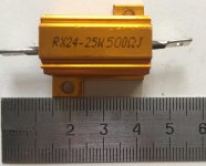
A very good result is the choice of resistors R107,R207 with a tester for each amplifier channel using RX24. (pic)
with a nominal of 500 ohms, on measure ~ 430 ohms
Resistive current EL34 ~ 52mA
Attachments
Last edited:
That's AC volts across the heater pins on the tube sockets? If so, I think that's a problem.
You had one side of the heater wiring connected to circuit ground? Have you changed that? Do you now have the 'two resistors to make artificial center tap' wiring in place?
A quick sketch schematic of the heater wiring would help. You can just draw it on paper and post a picture here.
You had one side of the heater wiring connected to circuit ground? Have you changed that? Do you now have the 'two resistors to make artificial center tap' wiring in place?
A quick sketch schematic of the heater wiring would help. You can just draw it on paper and post a picture here.
Last edited:
- Home
- Amplifiers
- Tubes / Valves
- Boyuu EL34 A9 Tube Amp