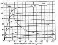
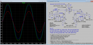
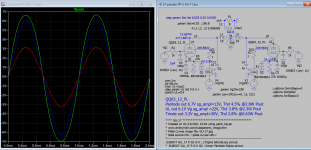
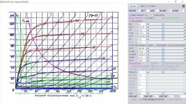
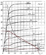
It looks like this model does not work correctly in both triode and pentode modes. Does anyone have any real curves in these modes? I have curves for the Soviet analogue GU17, but I'm not sure if they are correct either.Try this one, should be close enough...
Code:* * Generic pentode model: QQ03_12_AN * Copyright 2003--2008 by Ayumi Nakabayashi, All rights reserved. * Version 3.10, Generated on Sat Mar 07 19:15:37 2015 * Plate * | Screen Grid * | | Control Grid * | | | Cathode * | | | | .SUBCKT QQ03_12_AN A G2 G1 K BGG GG 0 V=V(G1,K)+1 BM1 M1 0 V=(0.10806033*(URAMP(V(G2,K))+1e-10))**-1.4768137 BM2 M2 0 V=(0.50389449*(URAMP(V(GG)+URAMP(V(G2,K))/4.5910051)))**2.9768137 BP P 0 V=0.0012268646*(URAMP(V(GG)+URAMP(V(G2,K))/9.1110445))**1.5 BIK IK 0 V=U(V(GG))*V(P)+(1-U(V(GG)))*0.0011989613*V(M1)*V(M2) BIG IG 0 V=0.0006134323*URAMP(V(G1,K))**1.5*(URAMP(V(G1,K))/(URAMP(V(A,K))+URAMP(V(G1,K)))*1.2+0.4) BIK2 IK2 0 V=V(IK,IG)*(1-0.4*(EXP(-URAMP(V(A,K))/URAMP(V(G2,K))*15)-EXP(-15))) BIG2T IG2T 0 V=V(IK2)*(0.87112107*(1-URAMP(V(A,K))/(URAMP(V(A,K))+10))**1.5+0.12887893) BIK3 IK3 0 V=V(IK2)*(URAMP(V(A,K))+22300)/(URAMP(V(G2,K))+22300) BIK4 IK4 0 V=V(IK3)-URAMP(V(IK3)-(0.00082086248*(URAMP(V(A,K))+URAMP(URAMP(V(G2,K))-URAMP(V(A,K))))**1.5)) BIP IP 0 V=URAMP(V(IK4,IG2T)-URAMP(V(IK4,IG2T)-(0.00082086248*URAMP(V(A,K))**1.5))) BIAK A K I=V(IP)+1e-10*V(A,K) BIG2 G2 K I=URAMP(V(IK4,IP)) BIGK G1 K I=V(IG) * CAPS CGA G1 A 0.1p CGK G1 K 3.7p C12 G1 G2 2.5p CAK A K 2.6p .ENDS
Attachments
Anyone ever tried to build a QQE 06/40 tetrode? https://frank.pocnet.net/sheets/128/5/5894.pdf
Thanks!
Thanks!
https://www.hi-fi.ru/audioportal/up...-17_.jpg.1716091b796e98dd21f7b6ee70413d7f.jpg
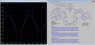
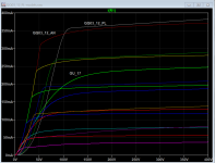
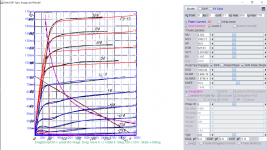
I remodeled GU-17 using the above more extended curve here is the updated model:
I remodeled GU-17 using the above more extended curve here is the updated model:
Code:
*** GU_17 ******************************************
* Created on 01/14/2021 17:29 using paint_kip.jar
* [URL="http://www.dmitrynizh.com/tubeparams_image.htm"]Model Paint Tools: Trace Tube Parameters over Plate Curves, Interactively[/URL]
* Plate Curves image file: GU-17.jpg
* Data source link: <plate curves URL>
*----------------------------------------------------------------------------------
.SUBCKT GU_17 P G2 G K ; LTSpice tetrode.asy pinout
* .SUBCKT GU_17 P G K G2 ; Koren Pentode Pspice pinout
+ PARAMS: MU=8.352 KG1=1802.71 KP=58.9 KVB=625.63 VCT=0.001082 EX=1.187 KG2=1800.08 KNEE=10.3 KVC=1.849
+ KLAM=5.88E-10 KLAMG=1.874E-4  KD=74.23 KC=5.645 KR1=7.67E-4 KR2=0.00384 KVBG=0.00825 KB1=2.58 KB2=2 KB3=2 KB4=0.3074 KVBGI=0.28 KNK=0.04211 KNG=0.01824 KNPL=0.04894 KNSL=12.94 KNPR=89.4 KNSR=68.45
+ CCG=6.2P CGP=2.6P CCP=1.9P VGOFF=-1 IGA=5.2E-4 IGB=0.27 IGC=13.92 IGEX=1.44
* Vp_MAX=350 Ip_MAX=170 Vg_step=5 Vg_start=20 Vg_count=11
* X_MIN=167 Y_MIN=33 X_SIZE=486 Y_SIZE=595 FSZ_X=1296 FSZ_Y=736 XYGrid=true
* Rp=1400 Vg_ac=20 P_max=6 Vg_qui=-5 Vp_qui=300
* showLoadLine=n showIp=y isDHP=n isPP=n isAsymPP=n isUL=n showDissipLimit=y
* showIg1=y isInputSnapped=y addLocalNFB=n
* XYProjections=n harmonicPlot=y dissipPlot=n
* UL=0.43 EG2=200 gridLevel2=y addKink=y isTanhKnee=n advSigmoid=y
*----------------------------------------------------------------------------------
RE1  7 0  1G    ; DUMMY SO NODE 7 HAS 2 CONNECTIONS
E1   7 0  VALUE=  ; E1 BREAKS UP LONG EQUATION FOR G1.
+{V(G2,K)/KP*LOG(1+EXP((1/MU+(VCT+V(G,K))/SQRT(KVB+V(G2,K)*V(G2,K)))*KP))}
RE2  6 0  1G    ; DUMMY SO NODE 6 HAS 2 CONNECTIONS
E2  6 0  VALUE={(PWR(V(7),EX)+PWRS(V(7),EX))} ; Kg1 times KIT current
E4   8 0  VALUE={V(P,K)/KNEE/(KVBGI+V(6)*KVBG)}
E5  81 0  VALUE={PWR(V(8),KB1)}
E6  82 0  VALUE={PWR(V(8),KB2)}
E7  83 0  VALUE={PWR(V(8),KB3)}
E8   9 0  VALUE={PWR(1-EXP(-V(81)*(KC+KR1*V(82))/(KD+KR2*V(83))),KB4)*1.5708}
RE4  8 0  1
RE5 81 0  1
RE6 82 0  1
RE7 83 0  1
RE8  9 0  1
RE21 21 0 1
E21  21 0 VALUE={V(6)/KG1*V(9)} ; Ip with knee but no slope and no kink
RE22 22 0 1 ; E22: kink curr deviation for plate
E22  22 0 VALUE={V(21)*LIMIT(KNK-V(G,K)*KNG,0,0.3)*(-ATAN((V(P,K)-KNPL)/KNSL)+ATAN((V(P,K)-KNPR)/KNSR))}
G1   P K  VALUE={V(21)*(1+KLAMG*V(P,K))+KLAM*V(P,K) + V(22)}
G2   G2 K  VALUE={V(6)/KG2*(KVC-V(9))/(1+KLAMG*V(P,K)) - V(22)}
RCP  P K  1G     ; FOR CONVERGENCE
C1   K G  {CCG}  ; CATHODE-GRID 1
C2   G P  {CGP}  ; GRID 1-PLATE
C3   K P  {CCP}  ; CATHODE-PLATE
RE23 G 0 1G
GG G K VALUE={(IGA+IGB/(IGC+V(P,K)))*(MU/KG1)*
+(PWR(V(G,K)-VGOFF,IGEX)+PWRS(V(G,K)-VGOFF,IGEX))}
.ENDS
*$
Attachments
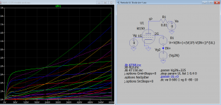
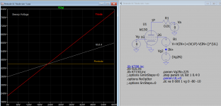
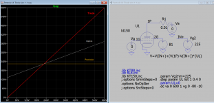
I modified my version using BV source it works too. Thank for the good work.
The mod is to subtract V(IN+) from Plate sweeping source, is the same as when E1 ground is connected to the top of Vg2 in your sch.
V=V(IN+)+(V(1P)-V(IN+))*{UL}
The mod is to subtract V(IN+) from Plate sweeping source, is the same as when E1 ground is connected to the top of Vg2 in your sch.
V=V(IN+)+(V(1P)-V(IN+))*{UL}
Attachments
Last edited:
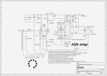
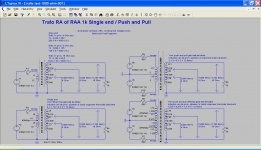
There are a variety of output transformer models for different applications.
Could you improve these models? For example, it would be much clearer and more convenient if the number of turns in the windings and only then their inductance were indicated.
Could you improve these models? For example, it would be much clearer and more convenient if the number of turns in the windings and only then their inductance were indicated.
Attachments
A 6N1P model from Adrian will be great to have. Looking forward to that. (...)
Hi rongon
Here it is...
My 6N1P model is based on a "golden sample" out of 10 triodes, each burned in for 100 hours. The bunch of 6N1P's had surprisingly tight manufacturing tolerances (the closest I recognized ever), especially regarding plate resistance.
Note that real 6N1P samples behave significantly different compared to what the data sheet claims:
- mu tends to be larger in real samples (typically 42 instead of 35)
- contact potential in real samples is 1.5-2V (!!) lower than the data sheet says
How ever, I really like this soviet "workhorse" - robust, tight tolerances, and well glowing
 .
.cheers, Adrian
Code:
*6N1P LTspice model based on the generic triode model from Adrian Immler, version i4
*A version log is at the end of this file
*100h BurnIn of 5 Voskhod factory tubes, sample selection and measurements done in Jan. 2021
*Params fitted to the measured values by Adrian Immler, Jan. 2021
*The high fit quality is presented at adrianimmler.simplesite.com
*History's best of tube decribing art (plus some new ideas) is merged to this new approach.
*@ neg. Vg, Ia accuracy is similar to Koren models.
*@ small neg. Vg, the "Anlauf" current is considered.
*@ pos. Vg, Ig and Ia accuracy is on a unrivaled level.
*This offers new simulation possibilities like bias point setting with MOhm grid resistor,
*Audion radio circuits, low voltage amps, guitar distortion stages or pulsed stages.
* anode (plate)
* | grid
* | | cathode
* | | |
.subckt 6N1P.i4 A G K
+ params:
*Parameters for the space charge current @ Vg <= 0
+ mu = 42.5 ;Determines the voltage gain @ constant Ia
+ rad = 6k1 ;Differential anode resistance, set @ Iad and Vg=0V
+ Vct = -0.5 ;Offsets the Ia-traces on the Va axis. Electrode material's contact potential
+ kp = 295 ;Mimics the island effect
+ xs = 1.5 ;Determines the curve of the Ia traces. Typically between 1.2 and 1.8
*
*Parameters for assigning the space charge current to Ia and Ig @ Vg > 0
+ kB = 0.6 ;Describes how fast Ia drops to zero when Va approaches zero.
+ radl = 300 ;Differential resistance for the Ia emission limit @ very small Va and Vg > 0
+ tsh = 20 ;Ia transmission sharpness from 1th to 2nd Ia area. Keep between 3 and 20. Start with 20.
+ xl = 1.2 ;Exponent for the emission limit
*
*Parameters of the grid-cathode vacuum diode
+ kvdg = 60 ;virtual vacuumdiode. Causes an Ia reduction @ Ig > 0.
+ kg = 3k55 ;Inverse scaling factor for the Va independent part of Ig (caution - interacts with xg!)
+ Vctg = 0.45 ;Offsets the log Ig-traces on the Vg axis. Electrode material's contact potential
+ xg = 1.9 ;Determines the curve of the Ig slope versus (positive) Vg and Va >> 0
+ VT = 0.092;Log(Ig) slope @ Vg<0. VT=k/q*Tk (cathodes absolute temp, typically 1150K)
+ kVT=0 ;Va dependant koeff. of VT
+ Vft2 = 0 gft2 = 0 ;finetunes the gridcurrent @ low Va and Vg near zero
*
*Parameters for the caps
+ cag = 2p7 ;From datasheet
+ cak = 1p7 ;From datasheet
+ cgk = 3p1 ;From datasheet
*
*special purpose parameters
+ os = 1 ;Overall scaling factor, if a user wishes to simulate manufacturing tolerances
*
*Calculated parameters
+ Iad = {100/rad} ;Ia where the anode a.c. resistance is set according to rad.
+ ks = {pow(mu/(rad*xs*Iad**(1-1/xs)),-xs)} ;Reduces the unwished xs influence to the Ia slope
+ ksnom = {pow(mu/(rad*1.5*Iad**(1-1/1.5)),-1.5)} ;Sub-equation for calculating Vg0
+ Vg0 = {Vct + (Iad*ks)**(1/xs) - (Iad*ksnom)**(2/3)} ;Reduces the xs influence to Vct.
+ kl = {pow(1/(radl*xl*Ild**(1-1/xl)),-xl)} ;Reduces the xl influence to the Ia slope @ small Va
+ Ild = {sqrt(radl)*1m} ;Current where the Il a.c. resistance is set according to radl.
*
*Space charge current model
Bggi GGi 0 V=v(Gi,K)+Vg0 ;Effective internal grid voltage.
Bahc Ahc 0 V=uramp(v(A,K)) ;Anode voltage, hard cut to zero @ neg. value
Bst St 0 V=uramp(max(v(GGi)+v(A,K)/(mu), v(A,K)/kp*ln(1+exp(kp*(1/mu+v(GGi)/(1+v(Ahc)))))));Steering volt.
Bs Ai K I=os/ks*pow(v(St),xs) ;Langmuir-Childs law for the space charge current Is
*
*Anode current limit @ small Va
.func smin(z,y,k) {pow(pow(z+1f, -k)+pow(y+1f, -k), -1/k)} ;Min-function with smooth trans.
Ra A Ai 1
Bgl Gi A I=min(i(Ra)-smin(1/kl*pow(v(Ahc),xl),i(Ra),tsh),i(Bgvd)*exp(4*v(G,K))) ;Ia emission limit
*
*Grid model
Bvdg G Gi I=1/kvdg*pwrs(v(G,Gi),1.5) ;Reduces the internal effective grid voltage when Ig rises
Rgip G Gi 1G ;avoids some warnings
Cvdg G Gi 0p1;this small cap improves convergence
.func fVT() {VT*exp(-kVT*sqrt(v(A,K)))}
.func Ivd(Vvd, kvd, xvd, VTvd) {if(Vvd < 3, 1/kvd*pow(VTvd*xvd*ln(1+exp(Vvd/VTvd/xvd)),xvd), 1/kvd*pow(Vvd, xvd))} ;Vacuum diode function
Bgvd Gi K I=Ivd(v(G,K) + Vctg, kg/os, xg, fVT())
.func ft2() {gft2*(1-tanh(3*(v(G,K)+Vft2)))} ;Finetuning-func. improves ig-fit @ Vg near -0.5V, low Va.
Bgr Gi Ai I=ivd(v(GGi),ks/os, xs, 0.8*VT)/(1+ft2()+kB*v(Ahc));Is reflection to grid when Va approaches zero
Bs0 Ai K I=ivd(v(GGi),ks/os, xs, 0.8*VT)/(1+ft2()) - os/ks*pow(v(GGi),xs) ;Compensates neg Ia @ small Va and Vg near zero
*
*Caps
C1 A G {cag}
C2 A K {cak}
C3 G K {cgk}
.ends
*
*Version log
*i1 :Initial version
*i2 :Pin order changed to the more common order âA G Kâ (Thanks to Markus Gyger for his tip)
*i3 :bugfix of the Ivd-function: now also usable for larger Vvd
*i4: Rgi replaced by a virtual vacuum diode (better convergence). ft1 deleted (no longer needed)
;2 new prarams for Ig finetuning @ Va and Vg near zero. New emission skaling factor ke for aging etc.Attachments
...My 6N1P model is ....
Thanks.
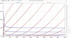
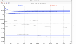
The 833a tube model provided by Koonw cannot be simulated correctly. What is the prob
Here is 833 model:
Code:*** 833A_SOV ** Advanced Grid Current ********************************** * Created on 07/15/2020 19:44 using paint_kit.jar 3.1 * [URL="http://www.dmitrynizh.com/tubeparams_image.htm"]www.dmitrynizh.com/tubeparams_image.htm[/URL] * Plate Curves image file: 833a-sov.png * Data source link: *---------------------------------------------------------------------------------- .SUBCKT 833A_SOV 1 2 3 ; Plate Grid Cathode + PARAMS: CCG=3P CGP=1.4P CCP=1.9P + MU=35 KG1=92708.35 KP=757.68 KVB=53609.84 VCT=-23.31 EX=0.914 + VGOFF=-4.2 IGA=0 IGB=0.089 IGC=876.62 IGEX=1.659 * Vp_MAX=4000 Ip_MAX=5 Vg_step=50 Vg_start=350 Vg_count=10 * Rp=4000 Vg_ac=55 P_max=400 Vg_qui=-48 Vp_qui=300 * X_MIN=37 Y_MIN=36 X_SIZE=837 Y_SIZE=489 FSZ_X=1296 FSZ_Y=736 XYGrid=false * showLoadLine=n showIp=y isDHT=n isPP=n isAsymPP=n showDissipLimit=y * showIg1=y gridLevel2=y isInputSnapped=n * XYProjections=n harmonicPlot=n dissipPlot=n *---------------------------------------------------------------------------------- E1 7 0 VALUE={V(1,3)/KP*LOG(1+EXP(KP*(1/MU+(VCT+V(2,3))/SQRT(KVB+V(1,3)*V(1,3)))))} RE1 7 0 1G ; TO AVOID FLOATING NODES G1 1 3 VALUE={(PWR(V(7),EX)+PWRS(V(7),EX))/KG1} RCP 1 3 1G ; TO AVOID FLOATING NODES C1 2 3 {CCG} ; CATHODE-GRID C2 2 1 {CGP} ; GRID=PLATE C3 1 3 {CCP} ; CATHODE-PLATE RE2 2 0 1G EGC 8 0 VALUE={V(2,3)-VGOFF} ; POSITIVE GRID THRESHOLD GG 2 3 VALUE={(IGA+IGB/(IGC+V(1,3)))*(MU/KG1)*(PWR(V(8),IGEX)+PWRS(V(8),IGEX))} .ENDS *$

Try this FU33 model, I'll look into 833a model:
Code:
**** FU33 ** Advanced Grid Current **********************************
* Created on 11/12/2020 18:31 using paint_kit.jar 3.1
* [URL="http://www.dmitrynizh.com/tubeparams_image.htm"]www.dmitrynizh.com/tubeparams_image.htm[/URL]
* Plate Curves image file: fu33.png
* Data source link:
*----------------------------------------------------------------------------------
.SUBCKT FU33 1 2 3 ; Plate Grid Cathode
+ PARAMS: CCG=3P  CGP=1.4P CCP=1.9P
+ MU=30.4 KG1=209 KP=15917.44 KVB=26880 VCT=-30.72 EX=1.056
+ VGOFF=-8.96 IGA=1.75E-5 IGB=0.021 IGC=0.64 IGEX=1.66
* Vp_MAX=4000 Ip_MAX=5000 Vg_step=50 Vg_start=350 Vg_count=11
* Rp=4000 Vg_ac=55 P_max=300 Vg_qui=-48 Vp_qui=300
* X_MIN=38 Y_MIN=40 X_SIZE=806 Y_SIZE=505 FSZ_X=1296 FSZ_Y=736 XYGrid=true
* showLoadLine=n showIp=y isDHT=n isPP=n isAsymPP=n showDissipLimit=y
* showIg1=y gridLevel2=y isInputSnapped=n
* XYProjections=n harmonicPlot=n dissipPlot=n
*----------------------------------------------------------------------------------
E1 7 0 VALUE={V(1,3)/KP*LOG(1+EXP(KP*(1/MU+(VCT+V(2,3))/SQRT(KVB+V(1,3)*V(1,3)))))}
RE1 7 0 1G  ; TO AVOID FLOATING NODES
G1 1 3 VALUE={(PWR(V(7),EX)+PWRS(V(7),EX))/KG1}
RCP 1 3 1G   ; TO AVOID FLOATING NODES
C1 2 3 {CCG} ; CATHODE-GRID
C2 2 1 {CGP} ; GRID=PLATE
C3 1 3 {CCP} ; CATHODE-PLATE
RE2 2 0 1G
EGC 8 0 VALUE={V(2,3)-VGOFF} ; POSITIVE GRID THRESHOLD
GG 2 3 VALUE={(IGA+IGB/(IGC+V(1,3)))*(MU/KG1)*(PWR(V(8),IGEX)+PWRS(V(8),IGEX))}
.ENDS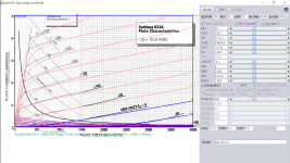
*$833a_sov model fixed (corrected the Ia scale on the left):
Code:
**** 833A_SOV ** Advanced Grid Current **********************************
* Created on 01/19/2021 12:24 using paint_kit.jar 3.1
* [URL="http://www.dmitrynizh.com/tubeparams_image.htm"]Model Paint Tools: Trace Tube Parameters over Plate Curves, Interactively[/URL]
* Plate Curves image file: 833a-sov.png
* Data source link:
*----------------------------------------------------------------------------------
.SUBCKT 833A_SOV 1 2 3 ; Plate Grid Cathode
+ PARAMS: CCG=12.3P  CGP=6.3P CCP=9.5P
+ MU=35 KG1=246.2 KP=1173.2 KVB=53904.8 VCT=-12.59 EX=1.075
+ VGOFF=-4.2 IGA=0 IGB=0.089 IGC=876.62 IGEX=1.659
* Vp_MAX=4000 Ip_MAX=5000 Vg_step=50 Vg_start=350 Vg_count=10
* Rp=4000 Vg_ac=55 P_max=400 Vg_qui=-48 Vp_qui=300
* X_MIN=63 Y_MIN=43 X_SIZE=788 Y_SIZE=493 FSZ_X=1296 FSZ_Y=736 XYGrid=false
* showLoadLine=n showIp=y isDHT=n isPP=n isAsymPP=n showDissipLimit=y
* showIg1=y gridLevel2=y isInputSnapped=n
* XYProjections=n harmonicPlot=n dissipPlot=n
*----------------------------------------------------------------------------------
E1 7 0 VALUE={V(1,3)/KP*LOG(1+EXP(KP*(1/MU+(VCT+V(2,3))/SQRT(KVB+V(1,3)*V(1,3)))))}
RE1 7 0 1G  ; TO AVOID FLOATING NODES
G1 1 3 VALUE={(PWR(V(7),EX)+PWRS(V(7),EX))/KG1}
RCP 1 3 1G   ; TO AVOID FLOATING NODES
C1 2 3 {CCG} ; CATHODE-GRID
C2 2 1 {CGP} ; GRID=PLATE
C3 1 3 {CCP} ; CATHODE-PLATE
RE2 2 0 1G
EGC 8 0 VALUE={V(2,3)-VGOFF} ; POSITIVE GRID THRESHOLD
GG 2 3 VALUE={(IGA+IGB/(IGC+V(1,3)))*(MU/KG1)*(PWR(V(8),IGEX)+PWRS(V(8),IGEX))}
.ENDS
*$
Attachments
Last edited:
- Home
- Amplifiers
- Tubes / Valves
- Vacuum Tube SPICE Models