Hi Sorento,PL508 Siemens, brand new out of box:
Va / Vg2 / Ia / Ig2 in that order, Vg1 = -18V (just two used 9V batteries in series)
190V / 190V / 61mA / 4.8mA
200V / 200V / 72mA / 5.7mA
210V / 210V / 91mA / 7.2mA
220V / 220V / 107mA / 8.6mA
250V / 200V / 76mA / 4.3mA
275V / 195V / 70mA / 3.4mA
300V / 130V / 39mA / 1.3mA
I'm back on DiyAudio after a gap of several years, I've been discussing automotive Class D amps, but have taken time to visit my old love, vacuum tube simulations.
Where are you obtaining Plate and Screen voltages for your PL508? Years ago, as part of my experiments, I was hoping to mod a Tektronix Transistor Curve Tracer for use with vacuum tubes. They were like jelly beans on the benches in our Audio Group, but the division closed, selling them and dozens of Audio Precision 2700 Analyzers, surplus, before I could get my hands on any.
I've been using some complex LTSpice simulations, with convergence issues for years. One of my tongue-in-cheek written descriptions is How to Emulate a Pentode Vacuum Tube With Only 28 Op Amps, 40 Transistors and 156 Passive Discretes, along with a genesis and some simple math on how various tube types developed. Once I do some cleanup, I hope to publish them, possibly here.
My Best,
Ron
Try this EF80 (Philips) model:
Code:
**** EF80 ******************************************
* Created on 05/28/2022 00:14 using paint_kip.jar
* www.dmitrynizh.com/tubeparams_image.htm
* Plate Curves image file: ef80.png
* Data source link: <plate curves URL>
*-------------------------------------------------------------posted---------------------
.SUBCKT EF80 P G2 G K ; LTSpice tetrode.asy pinout
* .SUBCKT EF80 P G K G2 ; Koren Pentode Pspice pinout
+ PARAMS: MU=51.5 KG1=737.47 KP=186.79 KVB=1085.66 VCT=0.2779 EX=1.558 KG2=724.57 KNEE=963.53 KVC=1.795
+ KLAMG=1.102E-4  KD=118.44 KC=571.64 KR1=0.00625 KR2=0.1745 KVBG=0.008104 KB1=0.908 KB2=0.01702 KB3=0.00625 KB4=3.442 KVBGI=0.04391 KNK=0.05906 KNG=1.122E-4 KNPL=0.3353 KNSL=0.07806 KNPR=621.29 KNSR=5.842E6
+ CCG=7.5P CGP=3.3P CCP=0.012P VGOFF=-0.6 IGA=3E-10 IGB=0.02556 IGC=20 IGEX=1.413
* Vp_MAX=350 Ip_MAX=35 Vg_step=1 Vg_start=0 Vg_count=10
* X_MIN=58 Y_MIN=202 X_SIZE=746 Y_SIZE=406 FSZ_X=1296 FSZ_Y=736 XYGrid=false
* Rp=1600 Vg_ac=23.5 P_max=2.5 Vg_qui=-23.4 Vp_qui=240
* showLoadLine=n showIp=y isDHP=n isPP=n isAsymPP=n isUL=n showDissipLimit=y
* showIg1=y isInputSnapped=n addLocalNFB=n
* XYProjections=n harmonicPlot=y dissipPlot=n
* UL=0.43 EG2=170 gridLevel2=y addKink=y isTanhKnee=n advSigmoid=y
*----------------------------------------------------------------------------------
RE1  7 0  1G    ; DUMMY SO NODE 7 HAS 2 CONNECTIONS
E1   7 0  VALUE=  ; E1 BREAKS UP LONG EQUATION FOR G1.
+{V(G2,K)/KP*LOG(1+EXP((1/MU+(VCT+V(G,K))/SQRT(KVB+V(G2,K)*V(G2,K)))*KP))}
RE2  6 0  1G    ; DUMMY SO NODE 6 HAS 2 CONNECTIONS
E2  6 0  VALUE={(PWR(V(7),EX)+PWRS(V(7),EX))} ; Kg1 times KIT current
E4   8 0  VALUE={V(P,K)/KNEE/(KVBGI+V(6)*KVBG)}
E5  81 0  VALUE={PWR(V(8),KB1)}
E6  82 0  VALUE={PWR(V(8),KB2)}
E7  83 0  VALUE={PWR(V(8),KB3)}
E8   9 0  VALUE={PWR(1-EXP(-V(81)*(KC+KR1*V(82))/(KD+KR2*V(83))),KB4)*1.5708}
RE4  8 0  1
RE5 81 0  1
RE6 82 0  1
RE7 83 0  1
RE8  9 0  1
RE21 21 0 1
E21  21 0 VALUE={V(6)/KG1*V(9)} ; Ip with knee but no slope and no kink
RE22 22 0 1 ; E22: kink curr deviation for plate
E22  22 0 VALUE={V(21)*LIMIT(KNK-V(G,K)*KNG,0,0.3)*(-ATAN((V(P,K)-KNPL)/KNSL)+ATAN((V(P,K)-KNPR)/KNSR))}
G1   P K  VALUE={V(21)*(1+KLAMG*V(P,K)) + V(22)}
G2   G2 K  VALUE={V(6)/KG2*(KVC-V(9))/(1+KLAMG*V(P,K)) - V(22)}
RCP  P K  1G     ; FOR CONVERGENCE
C1   K G  {CCG}  ; CATHODE-GRID 1
C2   G P  {CGP}  ; GRID 1-PLATE
C3   K P  {CCP}  ; CATHODE-PLATE
RE23 G 0 1G
GG G K VALUE={(IGA+IGB/(IGC+V(P,K)))*(MU/KG1)*
+(PWR(V(G,K)-VGOFF,IGEX)+PWRS(V(G,K)-VGOFF,IGEX))}
.ENDS
*$
Attachments
Hi all
Here a small gift for those who like strong twin triodes: A 5687.i5 spice model!
As always, the i5 model is fitted to the most representative triode out of 10, all burnt-in for 100 hours.
In the lot of 5 tubes, there were different brands (Sylavania, PhilipsECG and Tungsol) but all shared the same electrode construction. So, I did not distinguish between different brands for the model.
BR Adrian
Code:
*5687 LTspice model based on the generic triode model from Adrian Immler, version i5
*A version log is at the end of this file
*100h BurnIn of 5 (Sylavania, PhilipsECG and Tungsol) tubes, sample selection and measurements done in April 2022
*Params fitted to the measured values by Adrian Immler, April 2022
*This model is accurate for Vg up to 4V, when Va is at least 5V.
*The high fit quality is presented at adrianimmler.simplesite.com
*History's best of tube describing art (plus some new ideas) is merged to this new approach.
*@ neg. Vg, Ia accuracy is similar to Koren models, and unrivaled for remote cutoff triodes
*@ small neg. Vg, the "Anlauf" current is considered.
*@ pos. Vg, Ig and Ia accuracy is on an unrivaled level (including neg. Va range!)
*This offers new simulation possibilities like grid resistor bias, backward plate modulated stages,
*Audion radio circuits, low voltage amps, guitar distortion stages or pulsed stages.
*            i5 version. All 5687s seen share the same construction (so, no company letters needed)
*            |  anode (plate)
*            |  | grid
*            |  | | cathode
*            |  | | |
.subckt 5687.i5 A G K
+ params:
*Parameters for space charge current Is (100% assigned to Ia @ Vg < 0)
+ mu   = 19.5  ;Determines the voltage gain @ constant Ia
+ rad  = 1k23  ;Differential anode resistance, set @ Iad and Vg=0V
+ Vct  = 0.3   ;Offsets the Ia-traces on the Va axis. Electrode material's contact potential
+ kp   = 115   ;Mimics the island effect
+ xs   = 1.5   ;Determines the curve of the Ia traces. Typically between 1.2 and 1.8
+ kIsr = 0     ;Va-independent part of the Is reduction when grid current occurs
+ kvdg  = 500  ;Va-dependent part of the Is reduction when grid current occurs
*
*Parameters for assigning the space charge current to Ia and Ig @ Vg > 0
+ kB   = 0.7   ;Describes how fast Ia drops to zero when Va approaches zero.
+ radl = 180   ;Differential resistance for the Ia emission limit @ very small Va and Vg > 0
+ tsh  = 8     ;Ia transmission sharpness from 1st to 2nd Ia area. Keep between 3 and 20. Start with 20.
+ xl   = 1.6   ;Exponent for the emission limit
*
*Parameters of the grid-cathode vacuum diode
+ kg = 780     ;Inverse scaling factor for the Va independent part of Ig (caution - interacts with xg!)
+ Vctg = -0.6  ;Offsets the log Ig-traces on the Vg axis. Electrode material's contact potential
+ xg   = 1.1   ;Determines the curve of the Ig slope versus (positive) Vg and Va >> 0
+ VT   = 0.134 ;Log(Ig) slope @ Vg<0. VT=k/q*Tk (cathodes absolute temp, typically 1150K)
+ rTr  = 0.6   ;ratio of VT for Igr. Typically 0.8
+ kVT= 20m     ;Va dependent koeff. of VT
+ gft1 = 0     ;reduces the steering voltage around Vg=-Vg0, for finetuning purposes
+ gft1a= 0.27  ;reduces the steering voltage around Vg=-Vg0. Effect decreases with 1/(1+kB*Va)
+ gft2 = 2     ;finetunes the Igr drop @ increasing Va and around Vg=-Vg0
*
*Parameters for the caps
+ cag  = 4p0   ;From datasheet
+ cak  = 0p6   ;From datasheet
+ cgk  = 4p0   ;From datasheet
*
*special purpose parameters
+ os = 1       ;Overall scaling factor, if a user wishes to simulate manufacturing tolerances
+ murc = 10    ;Mu of the remote cutoff triode
+ ksrc = 1G    ;Inverse Iarc gain factor for the remote cutoff triode
+ kprc = 55    ;Mimics the island effect for the remote cutoff triode
+ Vbatt = 0    ;heater battery voltage for direct heated battery triodes
+ Vdrmax = 2.8 ;max voltage of internal Vg drop, for convergence improvements
*
*Calculated parameters
+ Iad = {100/rad} ;Ia where the anode a.c. resistance is set according to rad.
+ ks = {pow(mu/(rad*xs*Iad**(1-1/xs)),-xs)} ;Reduces the unwished xs influence to the Ia slope
+ ksnom = {pow(mu/(rad*1.5*Iad**(1-1/1.5)),-1.5)} ;Sub-equation for calculating Vg0
+ Vg0 = {Vct + (Iad*ks)**(1/xs) - (Iad*ksnom)**(2/3)} ;Reduces the xs influence to Vct.
+ kl = {pow(1/(radl*xl*Ild**(1-1/xl)),-xl)} ;Reduces the xl influence to the Ia slope @ small Va
+ Ild = {sqrt(radl)*1m} ;Current where the Il a.c. resistance is set according to radl.
*
*Space charge current model
Rak A K 100G ;avoids "floating net" errors
Bft   ft 0 V=1/(1+pow(2*abs(v(G,Ki)+Vg0),3)) ;an auxiliary voltage to finetune the triode around Vg=-Vg0
Bggi GGi 0 V=(v(Gi,Ki)+Vg0)*(1/(1+kIsr*max(0, v(G,Ki)+Vg0))) - gft1*v(ft) - gft1a*v(ft)/(1+kB*v(Ahc)) ;Effective internal grid voltage.
Bahc Ahc 0 V=uramp(v(A,Ki)) ;Anode voltage, hard cut to zero @ neg. value
Bst   St 0 V=uramp(max(v(GGi)+v(A,Ki)/(mu), v(A,Ki)/kp*ln(1+exp(kp*(1/mu+v(GGi)/(1+v(Ahc)))))));Steering volt.
Bs    Ai Ki I=os/ks*pow(v(St),xs) ;Langmuir-Childs law for the space charge current Is
*Bstrc Strc 0 V=uramp(max(v(GGi)+v(Ahc)/(murc), v(Ahc)/kprc*ln(1+exp(kprc*(1/murc+v(GGi)/(1+v(Ahc)))))));FOR REMOTE CUTOFF TUBES ONLY
*Bsrc   Ai Ki I=os/ksrc*pow(v(Strc),xs) ;FOR REMOTE CUTOFF TUBES ONLY
*
*Anode current limit @ small Va
.func smin(z,y,k) {pow(pow(z+1f, -k)+pow(y+1f, -k), -1/k)} ;Min-function with smooth trans.
.func ssmin(z,y,k) {min(min(z,y), smin(z*1.003,y*1.003,k))};smin-function which suppresses small residual differences
Ra  A Ai 1
Bgl Gi A I=uramp(i(Ra)-ssmin(1/kl*pow(v(Ahc),xl),i(Ra),tsh)) ;Ia emission limit
*
*Grid model
Rgk G K 10G ;avoids "floating net" errors
Bvdg G Gi I=1/kvdg*pow(v(G,Gi),1.5) ;Reduces the internal effective grid voltage when Ig rises
Bcoh G Gi I=pow(uramp(v(G,Gi)-Vdrmax),2) ;A convergence help which softly limits the internal Vg voltage drop.
Rgip G Gi 1G ;avoids some warnings
.func fVT() {VT*exp(-kVT*sqrt(v(A,Ki)))}
.func Ivd(Vvd, kvd, xvd, VTvd)  {if(Vvd < 3, 1/kvd*pow(VTvd*xvd*ln(1+exp(Vvd/VTvd/xvd)),xvd), 1/kvd*pow(Vvd, xvd))} ;Vacuum diode function
Bgvd G Ki I=Ivd(v(G,Ki) + Vctg + min(0,v(A,Ki)/mu), kg/os, xg, fVT()) ;limits the internal Vg for convergence reasons
Bstn Stn 0 V=v(GGi)+min(0,v(A,Ki))/mu ;special steering voltage, sensitive to negative Anode voltages only
Bgr Gi Ai I= ivd(v(Stn),ks/os, xs, rTr*fVT())/(1+(kB+v(ft)*gft2)*v(Ahc));Is reflection to grid when Va approaches zero
*Bgr Gi Ai I=(ivd(v(Stn),ks/os, xs, rTr*fVT())+os/ksrc*pow(v(GGi),xs))/(1+(kB+v(ft)*gft2)*v(Ahc));FOR REMOTE CUTOFF TUBES ONLY
Bs0 Ai Ki  I=uramp(ivd(v(Stn),ks/os, xs, rTr*fVT()) - os/ks*pow(v(Stn),xs))
Bbatt Ki K V=Vbatt/2 ;for battery heated triodes; Offsets the average cathode potential to the half heater battery voltage
*
*Caps
C1 A G {cag}
C2 A K {cak}
C3 G K {cgk}
.ends
*
*Version log
*i1 :Initial version
*i2 :Pin order changed to the more common order A G K (Thanks to Markus Gyger for his tip)
*i3 :bugfix of the Ivd-function: now also usable for larger Vvd
*i4: Rgi replaced by a virtual vacuum diode (better convergence). ft1 deleted (no longer needed)
;2 new params for Ig finetuning @ Va and Vg near zero. New overall scaling factor os for aging etc.
*i5: improved convergence performance. PosVg/NegVa area now correct. Also accurate now for remote cutoff triodes!
Attachments
Hi Koown,Try this EF80 (Philips) model:
Code:**** EF80 ****************************************** * Created on 05/28/2022 00:14 using paint_kip.jar * www.dmitrynizh.com/tubeparams_image.htm * Plate Curves image file: ef80.png * Data source link: <plate curves URL> *-------------------------------------------------------------posted--------------------- .SUBCKT EF80 P G2 G K ; LTSpice tetrode.asy pinout * .SUBCKT EF80 P G K G2 ; Koren Pentode Pspice pinout + PARAMS: MU=51.5 KG1=737.47 KP=186.79 KVB=1085.66 VCT=0.2779 EX=1.558 KG2=724.57 KNEE=963.53 KVC=1.795 + KLAMG=1.102E-4 KD=118.44 KC=571.64 KR1=0.00625 KR2=0.1745 KVBG=0.008104 KB1=0.908 KB2=0.01702 KB3=0.00625 KB4=3.442 KVBGI=0.04391 KNK=0.05906 KNG=1.122E-4 KNPL=0.3353 KNSL=0.07806 KNPR=621.29 KNSR=5.842E6 + CCG=7.5P CGP=3.3P CCP=0.012P VGOFF=-0.6 IGA=3E-10 IGB=0.02556 IGC=20 IGEX=1.413 * Vp_MAX=350 Ip_MAX=35 Vg_step=1 Vg_start=0 Vg_count=10 * X_MIN=58 Y_MIN=202 X_SIZE=746 Y_SIZE=406 FSZ_X=1296 FSZ_Y=736 XYGrid=false * Rp=1600 Vg_ac=23.5 P_max=2.5 Vg_qui=-23.4 Vp_qui=240 * showLoadLine=n showIp=y isDHP=n isPP=n isAsymPP=n isUL=n showDissipLimit=y * showIg1=y isInputSnapped=n addLocalNFB=n * XYProjections=n harmonicPlot=y dissipPlot=n * UL=0.43 EG2=170 gridLevel2=y addKink=y isTanhKnee=n advSigmoid=y *---------------------------------------------------------------------------------- RE1 7 0 1G ; DUMMY SO NODE 7 HAS 2 CONNECTIONS E1 7 0 VALUE= ; E1 BREAKS UP LONG EQUATION FOR G1. +{V(G2,K)/KP*LOG(1+EXP((1/MU+(VCT+V(G,K))/SQRT(KVB+V(G2,K)*V(G2,K)))*KP))} RE2 6 0 1G ; DUMMY SO NODE 6 HAS 2 CONNECTIONS E2 6 0 VALUE={(PWR(V(7),EX)+PWRS(V(7),EX))} ; Kg1 times KIT current E4 8 0 VALUE={V(P,K)/KNEE/(KVBGI+V(6)*KVBG)} E5 81 0 VALUE={PWR(V(8),KB1)} E6 82 0 VALUE={PWR(V(8),KB2)} E7 83 0 VALUE={PWR(V(8),KB3)} E8 9 0 VALUE={PWR(1-EXP(-V(81)*(KC+KR1*V(82))/(KD+KR2*V(83))),KB4)*1.5708} RE4 8 0 1 RE5 81 0 1 RE6 82 0 1 RE7 83 0 1 RE8 9 0 1 RE21 21 0 1 E21 21 0 VALUE={V(6)/KG1*V(9)} ; Ip with knee but no slope and no kink RE22 22 0 1 ; E22: kink curr deviation for plate E22 22 0 VALUE={V(21)*LIMIT(KNK-V(G,K)*KNG,0,0.3)*(-ATAN((V(P,K)-KNPL)/KNSL)+ATAN((V(P,K)-KNPR)/KNSR))} G1 P K VALUE={V(21)*(1+KLAMG*V(P,K)) + V(22)} G2 G2 K VALUE={V(6)/KG2*(KVC-V(9))/(1+KLAMG*V(P,K)) - V(22)} RCP P K 1G ; FOR CONVERGENCE C1 K G {CCG} ; CATHODE-GRID 1 C2 G P {CGP} ; GRID 1-PLATE C3 K P {CCP} ; CATHODE-PLATE RE23 G 0 1G GG G K VALUE={(IGA+IGB/(IGC+V(P,K)))*(MU/KG1)* +(PWR(V(G,K)-VGOFF,IGEX)+PWRS(V(G,K)-VGOFF,IGEX))} .ENDS *$
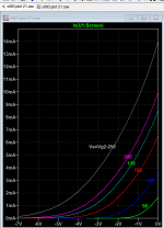
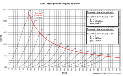
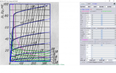
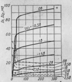
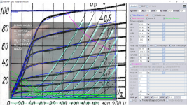
Apologies for my late feedback. I tried the model, but I get very different values compared to the curves in ef80_t.png. For example, the curves show 5mA for -4V bias and 200V plate voltage. I get 3mA:
Am I measuring this in the wrong way?
Thank you!
Jose
Hi all
Here a small gift for those who like strong twin triodes: A 5687.i5 spice model!...
Thank you Adrian! 5687 is one of my favorite tubes. Much appreciated.
The anode current of ef80_t consists of Ia +Ig2, you should also add Ig2 to Ia, by adding a trace like this:I tried the model, but I get very different values compared to the curves in ef80_t.png. For example, the curves show 5mA for -4V bias and 200V plate voltage. I get 3mA:
Ix(U1:Anode)+Ix(U1:Screen)
Or add a common resistor of 1m and measure the current through it.
I got almost 4ma, the difference is due to curve produce from different brand or by sample curve from the tracer is different from original datasheet or sometimes due to limitation or errors in modeling or tracing, you don't get to see the pentode curve with tracer when if only triode curve is traced.
I must admit Paint tools has reached the limitation for this model. If I follow ef80_t curve, I would get a different transfer curve from original.
Attachments
Last edited:
Yes, the same for me, especially regarding its beautiful glowing!(...) 5687 is one of my favorite tubes. (...)
")
Attachments
You are right, I should have measured the full current for triode mode, not just the plate. I get the same, as you, 3.8mA.The anode current of ef80_t consists of Ia +Ig2, you should also add Ig2 to Ia, by adding a trace like this:
Ix(U1:Anode)+Ix(U1:Screen)
Or add a common resistor of 1m and measure the current through it.
I got almost 4ma, the difference is due to curve produce from different brand or by sample curve from the tracer is different from original datasheet or sometimes due to limitation or errors in modeling or tracing, you don't get to see the pentode curve with tracer when if only triode curve is traced.
I must admit Paint tools has reached the limitation for this model. If I follow ef80_t curve, I would get a different transfer curve from original.
I have some questions that pertain to this thread posted over here at this thread.
https://www.diyaudio.com/community/...g-for-a-new-amp-build-i-am-working-on.386924/
just looking for some more exposure in hopes of some answers. Thank you.
https://www.diyaudio.com/community/...g-for-a-new-amp-build-i-am-working-on.386924/
just looking for some more exposure in hopes of some answers. Thank you.
Hi Sorento,
To continue - my 30 year on and off tube simulation effort was meant to have 3 phases:
1) math, using Mathcad, Excel or Microsoft Math,
2) schematic implementation in PSpice, LTSpice, TI TINA, etc,
3) generation of comparison tube curves, using a modified Tektronix curve tracer.
Simulation time has been quite limited. Since I more easily visualize sims in schematic form, most of my time has been spent doing phase 2) schematics. I've done several Pentodes, but it's been ages.
Unlike many of the sims I've seen, mine:
1) are truly physics-based, not just phenomenological,
2) duplicate and generate primary currents, although secondary currents are possible,
3) can handle a large number of positive and/or negative grids,
4) display currents for positive elements,
5) ease understanding of grids as true Faraday shields and
6) are generally differentiable, allowing small-signal analysis of any element, at any
operating point.
I've been using LTSpice, primarily because it's had fewer convergence issues than PSpice or TINA. Since a number of my simulations involve exponentiation, I prefer log/antilog techniques. Schematic SPICE simulations tend to choke on multiple log/antilogs. Fixing nonlinear convergence issues is a crap shoot. Global junction shunt conductances tend to screw up things.
Is anyone actually interested enough in doing some different schematic-based tube simulations? If so, I'll find time to clean up and describe what I have, allowing others to try.
I'm happy to answer any straightforward questions, as I find time.
Ron
210V / 210V / 91mA / 7.2mA
220V / 220V / 107mA / 8.6mA
250V / 200V / 76mA / 4.3mA
275V / 195V / 70mA / 3.4mA
300V / 130V / 39mA / 1.3mA
Click to expand...
To continue - my 30 year on and off tube simulation effort was meant to have 3 phases:
1) math, using Mathcad, Excel or Microsoft Math,
2) schematic implementation in PSpice, LTSpice, TI TINA, etc,
3) generation of comparison tube curves, using a modified Tektronix curve tracer.
Simulation time has been quite limited. Since I more easily visualize sims in schematic form, most of my time has been spent doing phase 2) schematics. I've done several Pentodes, but it's been ages.
Unlike many of the sims I've seen, mine:
1) are truly physics-based, not just phenomenological,
2) duplicate and generate primary currents, although secondary currents are possible,
3) can handle a large number of positive and/or negative grids,
4) display currents for positive elements,
5) ease understanding of grids as true Faraday shields and
6) are generally differentiable, allowing small-signal analysis of any element, at any
operating point.
I've been using LTSpice, primarily because it's had fewer convergence issues than PSpice or TINA. Since a number of my simulations involve exponentiation, I prefer log/antilog techniques. Schematic SPICE simulations tend to choke on multiple log/antilogs. Fixing nonlinear convergence issues is a crap shoot. Global junction shunt conductances tend to screw up things.
Is anyone actually interested enough in doing some different schematic-based tube simulations? If so, I'll find time to clean up and describe what I have, allowing others to try.
I'm happy to answer any straightforward questions, as I find time.
Ron
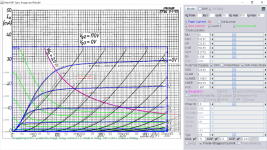
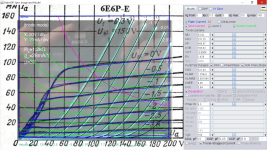
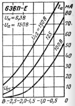
6e6p-e model, similar to 6e6p:
Code:
**** 6E6P_E ******************************************
* Created on 06/13/2022 18:29 using paint_kip.jar
* www.dmitrynizh.com/tubeparams_image.htm
* Plate Curves image file: 6e6p-e.png
* Data source link: <plate curves URL>
*----------------------------------------------------------------------------------
.SUBCKT 6E6P_E P G2 G K ; LTSpice tetrode.asy pinout
* .SUBCKT 6E6P_E P G K G2 ; Koren Pentode Pspice pinout
+ PARAMS: MU=33.92 KG1=231.25 KP=468.97 KVB=166.62 VCT=-0.8004 EX=1.428 KG2=521.03 KNEE=9.95 KVC=5.64
+ KLAM=1.25E-8 KLAMG=0.001094  KD=2.641E12 KC=20884.66 KR1=1459.8 KR2=2.154E-4 KVBG=0.008671 KB1=4.793 KB2=5.371E-5 KB3=1.6 KB4=0.368 KVBGI=-0.01113 KNK=0.007938 KNG=0.06088 KNPL=0.000984 KNSL=167.95 KNPR=93.74 KNSR=40.76
+ CCG=15P CGP=0.05P CCP=5.9P VGOFF=-0.6 IGA=0.001 IGB=0.3 IGC=8 IGEX=2
* Vp_MAX=200 Ip_MAX=160 Vg_step=0.5 Vg_start=0 Vg_count=9
* X_MIN=92 Y_MIN=53 X_SIZE=719 Y_SIZE=586 FSZ_X=1296 FSZ_Y=736 XYGrid=false
* Rp=1400 Vg_ac=20 P_max=8.3 Vg_qui=-2 Vp_qui=300
* showLoadLine=n showIp=y isDHP=n isPP=n isAsymPP=n isUL=n showDissipLimit=y
* showIg1=y isInputSnapped=y addLocalNFB=n
* XYProjections=n harmonicPlot=y dissipPlot=n
* UL=0.43 EG2=150 gridLevel2=y addKink=y isTanhKnee=n advSigmoid=y
*----------------------------------------------------------------------------------
RE1  7 0  1G    ; DUMMY SO NODE 7 HAS 2 CONNECTIONS
E1   7 0  VALUE=  ; E1 BREAKS UP LONG EQUATION FOR G1.
+{V(G2,K)/KP*LOG(1+EXP((1/MU+(VCT+V(G,K))/SQRT(KVB+V(G2,K)*V(G2,K)))*KP))}
RE2  6 0  1G    ; DUMMY SO NODE 6 HAS 2 CONNECTIONS
E2  6 0  VALUE={(PWR(V(7),EX)+PWRS(V(7),EX))} ; Kg1 times KIT current
E4   8 0  VALUE={V(P,K)/KNEE/(KVBGI+V(6)*KVBG)}
E5  81 0  VALUE={PWR(V(8),KB1)}
E6  82 0  VALUE={PWR(V(8),KB2)}
E7  83 0  VALUE={PWR(V(8),KB3)}
E8   9 0  VALUE={PWR(1-EXP(-V(81)*(KC+KR1*V(82))/(KD+KR2*V(83))),KB4)*1.5708}
RE4  8 0  1
RE5 81 0  1
RE6 82 0  1
RE7 83 0  1
RE8  9 0  1
RE21 21 0 1
E21  21 0 VALUE={V(6)/KG1*V(9)} ; Ip with knee but no slope and no kink
RE22 22 0 1 ; E22: kink curr deviation for plate
E22  22 0 VALUE={V(21)*LIMIT(KNK-V(G,K)*KNG,0,0.3)*(-ATAN((V(P,K)-KNPL)/KNSL)+ATAN((V(P,K)-KNPR)/KNSR))}
G1   P K  VALUE={V(21)*(1+KLAMG*V(P,K))+KLAM*V(P,K) + V(22)}
G2   G2 K  VALUE={V(6)/KG2*(KVC-V(9))/(1+KLAMG*V(P,K)) - V(22)}
RCP  P K  1G     ; FOR CONVERGENCE
C1   K G  {CCG}  ; CATHODE-GRID 1
C2   G P  {CGP}  ; GRID 1-PLATE
C3   K P  {CCP}  ; CATHODE-PLATE
RE23 G 0 1G
GG G K VALUE={(IGA+IGB/(IGC+V(P,K)))*(MU/KG1)*
+(PWR(V(G,K)-VGOFF,IGEX)+PWRS(V(G,K)-VGOFF,IGEX))}
.ENDS
*$
Attachments
6e5p new model:
Code:
**** 6E5P ******************************************
* Created on 06/13/2022 22:03 using paint_kip.jar
* www.dmitrynizh.com/tubeparams_image.htm
* Plate Curves image file: 6e5p.png
* Data source link: <plate curves URL>
*----------------------------------------------------------------------------------
.SUBCKT 6E5P P G2 G K ; LTSpice tetrode.asy pinout
* .SUBCKT 6E5P P G K G2 ; Koren Pentode Pspice pinout
+ PARAMS: MU=32.19 KG1=355.4 KP=224.68 KVB=69.42 VCT=-0.42 EX=1.688 KG2=1270.08 KNEE=10.86 KVC=2.987
+ KLAM=2E-6 KLAMG=0.000923  KD=653.37 KC=7196.6 KR1=1338.16 KR2=0.95 KVBG=0.4795 KB1=7.41 KB2=0.05 KB3=0.15 KB4=0.1527 KVBGI=-1.093 KNK=0.00178 KNG=0.02347 KNPL=0.4778 KNSL=0.001895 KNPR=56.55 KNSR=21.22
+ CCG=15P CGP=0.065P CCP=2.55P VGOFF=-0.6 IGA=0.001 IGB=0.3 IGC=8 IGEX=2
* Vp_MAX=240 Ip_MAX=130 Vg_step=0.5 Vg_start=0 Vg_count=9
* X_MIN=53 Y_MIN=25 X_SIZE=829 Y_SIZE=570 FSZ_X=1296 FSZ_Y=736 XYGrid=false
* Rp=1400 Vg_ac=20 P_max=8.3 Vg_qui=-2 Vp_qui=300
* showLoadLine=n showIp=y isDHP=n isPP=n isAsymPP=n isUL=n showDissipLimit=y
* showIg1=y isInputSnapped=y addLocalNFB=n
* XYProjections=n harmonicPlot=y dissipPlot=n
* UL=0.43 EG2=150 gridLevel2=y addKink=y isTanhKnee=n advSigmoid=y
*----------------------------------------------------------------------------------
RE1  7 0  1G    ; DUMMY SO NODE 7 HAS 2 CONNECTIONS
E1   7 0  VALUE=  ; E1 BREAKS UP LONG EQUATION FOR G1.
+{V(G2,K)/KP*LOG(1+EXP((1/MU+(VCT+V(G,K))/SQRT(KVB+V(G2,K)*V(G2,K)))*KP))}
RE2  6 0  1G    ; DUMMY SO NODE 6 HAS 2 CONNECTIONS
E2  6 0  VALUE={(PWR(V(7),EX)+PWRS(V(7),EX))} ; Kg1 times KIT current
E4   8 0  VALUE={V(P,K)/KNEE/(KVBGI+V(6)*KVBG)}
E5  81 0  VALUE={PWR(V(8),KB1)}
E6  82 0  VALUE={PWR(V(8),KB2)}
E7  83 0  VALUE={PWR(V(8),KB3)}
E8   9 0  VALUE={PWR(1-EXP(-V(81)*(KC+KR1*V(82))/(KD+KR2*V(83))),KB4)*1.5708}
RE4  8 0  1
RE5 81 0  1
RE6 82 0  1
RE7 83 0  1
RE8  9 0  1
RE21 21 0 1
E21  21 0 VALUE={V(6)/KG1*V(9)} ; Ip with knee but no slope and no kink
RE22 22 0 1 ; E22: kink curr deviation for plate
E22  22 0 VALUE={V(21)*LIMIT(KNK-V(G,K)*KNG,0,0.3)*(-ATAN((V(P,K)-KNPL)/KNSL)+ATAN((V(P,K)-KNPR)/KNSR))}
G1   P K  VALUE={V(21)*(1+KLAMG*V(P,K))+KLAM*V(P,K) + V(22)}
G2   G2 K  VALUE={V(6)/KG2*(KVC-V(9))/(1+KLAMG*V(P,K)) - V(22)}
RCP  P K  1G     ; FOR CONVERGENCE
C1   K G  {CCG}  ; CATHODE-GRID 1
C2   G P  {CGP}  ; GRID 1-PLATE
C3   K P  {CCP}  ; CATHODE-PLATE
RE23 G 0 1G
GG G K VALUE={(IGA+IGB/(IGC+V(P,K)))*(MU/KG1)*
+(PWR(V(G,K)-VGOFF,IGEX)+PWRS(V(G,K)-VGOFF,IGEX))}
.ENDS
*$
Attachments
Electro Harmonix 6922 model by Adrian Immler. EH 6922 is almost certainly a 6N23P-EV:
https://www.diyaudio.com/community/threads/vacuum-tube-spice-models.243950/page-147#post-6627629
GU50 model by Koonw
https://www.diyaudio.com/community/threads/vacuum-tube-spice-models.243950/page-162#post-6939149
https://www.diyaudio.com/community/threads/vacuum-tube-spice-models.243950/page-147#post-6627629
GU50 model by Koonw
https://www.diyaudio.com/community/threads/vacuum-tube-spice-models.243950/page-162#post-6939149
http://tehnodoka.ru/spravkalamp/6g23p.php
6e23p (6Ж23П) 6Zh23P model:
6e23p (6Ж23П) 6Zh23P model:
Code:
*** 6E23P *****************************posted************
* Created on 06/14/2022 07:49 using paint_kip.jar
* www.dmitrynizh.com/tubeparams_image.htm
* Plate Curves image file: 6e23p.png
* Data source link: <plate curves URL>
*----------------------------------------------------------------------------------
.SUBCKT 6E23P P G2 G K ; LTSpice tetrode.asy pinout
* .SUBCKT 6E23P P G K G2 ; Koren Pentode Pspice pinout
+ PARAMS: MU=43.52 KG1=146.34 KP=371.67 KVB=837.12 VCT=-0.81 EX=1.4 KG2=435.81 KNEE=12 KVC=2.677
+ KLAM=2E-6 KLAMG=4.838E-4  KD=9.229E16 KC=2.441E-5 KR1=1.148E-7 KR2=0.6752 KVBG=6.385E-4 KB1=8.043 KB2=0.01173 KB3=0.0918 KB4=0.2806 KVBGI=6.747E-5 KNK=0.02125 KNG=0.08169 KNPL=1.872 KNSL=1.608 KNPR=40.08 KNSR=53.64
+ CCG=14P CGP=0.15P CCP=3.5P VGOFF=-0.6 IGA=0.001 IGB=0.3 IGC=8 IGEX=2
* Vp_MAX=350 Ip_MAX=100 Vg_step=0.5 Vg_start=0 Vg_count=9
* X_MIN=108 Y_MIN=20 X_SIZE=446 Y_SIZE=639 FSZ_X=1296 FSZ_Y=736 XYGrid=false
* Rp=1400 Vg_ac=20 P_max=2.45 Vg_qui=-2 Vp_qui=300
* showLoadLine=n showIp=y isDHP=n isPP=n isAsymPP=n isUL=n showDissipLimit=y
* showIg1=y isInputSnapped=y addLocalNFB=n
* XYProjections=n harmonicPlot=y dissipPlot=n
* UL=0.43 EG2=150 gridLevel2=y addKink=y isTanhKnee=n advSigmoid=y
*----------------------------------------------------------------------------------
RE1  7 0  1G    ; DUMMY SO NODE 7 HAS 2 CONNECTIONS
E1   7 0  VALUE=  ; E1 BREAKS UP LONG EQUATION FOR G1.
+{V(G2,K)/KP*LOG(1+EXP((1/MU+(VCT+V(G,K))/SQRT(KVB+V(G2,K)*V(G2,K)))*KP))}
RE2  6 0  1G    ; DUMMY SO NODE 6 HAS 2 CONNECTIONS
E2  6 0  VALUE={(PWR(V(7),EX)+PWRS(V(7),EX))} ; Kg1 times KIT current
E4   8 0  VALUE={V(P,K)/KNEE/(KVBGI+V(6)*KVBG)}
E5  81 0  VALUE={PWR(V(8),KB1)}
E6  82 0  VALUE={PWR(V(8),KB2)}
E7  83 0  VALUE={PWR(V(8),KB3)}
E8   9 0  VALUE={PWR(1-EXP(-V(81)*(KC+KR1*V(82))/(KD+KR2*V(83))),KB4)*1.5708}
RE4  8 0  1
RE5 81 0  1
RE6 82 0  1
RE7 83 0  1
RE8  9 0  1
RE21 21 0 1
E21  21 0 VALUE={V(6)/KG1*V(9)} ; Ip with knee but no slope and no kink
RE22 22 0 1 ; E22: kink curr deviation for plate
E22  22 0 VALUE={V(21)*LIMIT(KNK-V(G,K)*KNG,0,0.3)*(-ATAN((V(P,K)-KNPL)/KNSL)+ATAN((V(P,K)-KNPR)/KNSR))}
G1   P K  VALUE={V(21)*(1+KLAMG*V(P,K))+KLAM*V(P,K) + V(22)}
G2   G2 K  VALUE={V(6)/KG2*(KVC-V(9))/(1+KLAMG*V(P,K)) - V(22)}
RCP  P K  1G     ; FOR CONVERGENCE
C1   K G  {CCG}  ; CATHODE-GRID 1
C2   G P  {CGP}  ; GRID 1-PLATE
C3   K P  {CCP}  ; CATHODE-PLATE
RE23 G 0 1G
GG G K VALUE={(IGA+IGB/(IGC+V(P,K)))*(MU/KG1)*
+(PWR(V(G,K)-VGOFF,IGEX)+PWRS(V(G,K)-VGOFF,IGEX))}
.ENDS
*$
Attachments
Here is correction of scale of 6e6p-e pentode mode:
** 6E6P_E *************************correction
** 6E6P_E *************************correction
-
Code:
Created on 06/15/2022 13:38 using paint_kip.jar
www.dmitrynizh.com/tubeparams_image.htm
Plate Curves image file: 6e6p-e.png
Data source link: <plate curves URL>

*----------------------------------------------------------------------------------
.SUBCKT 6E6P_E P G2 G K ; LTSpice tetrode.asy pinout
* .SUBCKT 6E6P_E P G K G2 ; Koren Pentode Pspice pinout
PARAMS: MU=35.62 KG1=189.62 KP=381.46 KVB=833.1 VCT=-0.8004 EX=1.342 KG2=588.76 KNEE=9.55 KVC=1.78
KLAM=1.25E-8 KLAMG=0.001335  KD=2.493E13 KC=3341.55 KR1=2580.93 KR2=3.533E-4 KVBG=0.004912 KB1=4.793 KB2=5.371E-5 KB3=1.6 KB4=0.1901 KVBGI=-1.022E-5 KNK=0.1727 KNG=0.1479 KNPL=0.00213 KNSL=17.2 KNPR=18.28 KNSR=26.21
CCG=15P CGP=0.05P CCP=5.9P VGOFF=-0.6 IGA=0.001 IGB=0.3 IGC=8 IGEX=2
Vp_MAX=200 Ip_MAX=100 Vg_step=0.5 Vg_start=0 Vg_count=9
X_MIN=76 Y_MIN=53 X_SIZE=715 Y_SIZE=599 FSZ_X=1296 FSZ_Y=736 XYGrid=false
Rp=1400 Vg_ac=20 P_max=10.5 Vg_qui=-2 Vp_qui=300
showLoadLine=n showIp=y isDHP=n isPP=n isAsymPP=n isUL=n showDissipLimit=y
showIg1=y isInputSnapped=y addLocalNFB=n
XYProjections=n harmonicPlot=y dissipPlot=n
UL=0.43 EG2=150 gridLevel2=y addKink=y isTanhKnee=n advSigmoid=y

*----------------------------------------------------------------------------------
RE1  7 0  1G    ; DUMMY SO NODE 7 HAS 2 CONNECTIONS
E1   7 0  VALUE=  ; E1 BREAKS UP LONG EQUATION FOR G1.
+{V(G2,K)/KP*LOG(1+EXP((1/MU+(VCT+V(G,K))/SQRT(KVB+V(G2,K)*V(G2,K)))*KP))}
RE2  6 0  1G    ; DUMMY SO NODE 6 HAS 2 CONNECTIONS
E2  6 0  VALUE={(PWR(V(7),EX)+PWRS(V(7),EX))} ; Kg1 times KIT current
E4   8 0  VALUE={V(P,K)/KNEE/(KVBGI+V(6)*KVBG)}
E5  81 0  VALUE={PWR(V(8),KB1)}
E6  82 0  VALUE={PWR(V(8),KB2)}
E7  83 0  VALUE={PWR(V(8),KB3)}
E8   9 0  VALUE={PWR(1-EXP(-V(81)*(KC+KR1*V(82))/(KD+KR2*V(83))),KB4)*1.5708}
RE4  8 0  1
RE5 81 0  1
RE6 82 0  1
RE7 83 0  1
RE8  9 0  1
RE21 21 0 1
E21  21 0 VALUE={V(6)/KG1*V(9)} ; Ip with knee but no slope and no kink
RE22 22 0 1 ; E22: kink curr deviation for plate
E22  22 0 VALUE={V(21)LIMIT(KNK-V(G,K)*KNG,0,0.3)(-ATAN((V(P,K)-KNPL)/KNSL)+ATAN((V(P,K)-KNPR)/KNSR))}
G1   P K  VALUE={V(21)*(1+KLAMG*V(P,K))+KLAM*V(P,K) + V(22)}
G2   G2 K  VALUE={V(6)/KG2*(KVC-V(9))/(1+KLAMG*V(P,K)) - V(22)}
RCP  P K  1G     ; FOR CONVERGENCE
C1   K G  {CCG}  ; CATHODE-GRID 1
C2   G P  {CGP}  ; GRID 1-PLATE
C3   K P  {CCP}  ; CATHODE-PLATE
RE23 G 0 1G
GG G K VALUE={(IGA+IGB/(IGC+V(P,K)))(MU/KG1)
+(PWR(V(G,K)-VGOFF,IGEX)+PWRS(V(G,K)-VGOFF,IGEX))}
.ENDS
*$
Attachments
- Home
- Amplifiers
- Tubes / Valves
- Vacuum Tube SPICE Models