Sorry I haven't been paying attention the past few days!
Sorry,
I have been really busy with Christmas comming soon and I am working several 24hr shifts back to back, I haven't been paying attention to the thread.
Nikon, I am glad you figured it out, I knew it had to be something causing the current not to flow through the KT88, it makes perfect sense now. Yes, with the selector in the null position, I do get similar readings (I had to try this after you mentioned it.
I found something I think you guys might find to be quite an exceptional upgrade to this circuit, particularaly at the position of the driver tube. The Basic CCS at K&K Audio, it sells for $8 per kit. I just received mine yesterday and put them together. Here they are: K & K Audio - Lundahl Transformers, audio DIY kits and more
I will have mine installed by tomorrow afternoon and will give report. The price is really good for what you get. The pieces seperately would cost half as much sans the PCB it comes with. The holes in the PCB are exactly the right size for a large finned heatsink to fit onto the PCB. It is really easy to set up....you can pre-adjust it before putting it into the circuit. The instructions show how to do this with a 9v battery, 10R resistor, and a multimeter.
I am even thinking of trying them on the power tube as well, I bought 4 to start with.
Merry Christmas,
Jeff
This article describes the connection of the first capacitor for a star grounded system like you suggest.
http://www.geofex.com/Article_Folders/stargnd/stargnd.htm
http://www.geofex.com/Article_Folders/stargnd/stargnd.htm
I'll post the other side tomorrow.
I was reading the it's advised to ground the first capacitor after the rectifier separetly from the other one. Any experience on this ?
D.
I was thinking to replace the choke, instead of putting a 10H with LCRC, put two 5H and LCLC keeping the capacitor I have. It's easier for me for mechanical reason and looking at the calculation in PSU2 will kill my hum.
Does it make sense ?
I am also puzzled about DC regulators. I have them set for 6.3 V DC, but with the tube connected I get a read of the voltage of only 3.2 V. I measured the resistance of the filament, and it's only 2 ohm. So it should mean that 1.6 A are flowing.
Does it mean it's working ?
Jeff, do your regulators behave like this ?
I did not try to connect HV with the DC yet.
Thanks,
Davide
SE KT88 Amp
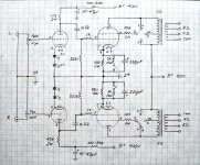
This is it! To keep things simple/pure (less R in signal path), I am going to use Glenn's version of the schematic with the addition of an RC filter (100R + 10-15uF) before the 6N1P plate for less ripple going to the driver. I am also going with an 2V LED cathode bias on the driver tube. I have some design and safety questions before final assembly:
1. Should the RC filter (100R + 15uF) have its own star ground or can it be shared with the tag board star ground?
2. Should the individual B+ for 6N1P and KT88's be twisted or can run parallel?
3. Can I have 1 shared RC or 2 separate RC filters going to the single 6N1P?
4. Does it matter if 5K ohm OPT primary goes to pin#3 on KT88 FIRST followed by a jumper to the mode switch?
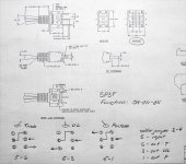
5. Please check for safety. I am using a Tyco SP3T 3A/250V toggle switch to control T, UL, P modes for each channel. Datasheet enclosed below and it states:
-Function: ON-ON-ON for the 3 positions
-Contacts are: 5-6 (up), 5-3 (center), 5-1 (down)
-"Customer installed external jumper between terminals 2 and 4 for 1 pole 3 throw function."
Does switch terminal #5 go to pin#4 of KT88 grid?...
Does switch terminal #6 go to Triode, #3 to UL, #1 to P mode?...
Nikon1975, according to PSUD2, and with my values of 5U4G-40uF-10H-50uF-100R-50uF, the CRCLC has 0.013V ripple, and the CLCRC has 0.014V ripple. I am not sure if we'll be able to hear 0.001V difference, let alone 20mV...
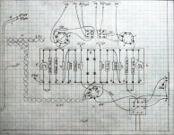
Here are my new schematics and new tag board layout.
Thanks guys!
This is it! To keep things simple/pure (less R in signal path), I am going to use Glenn's version of the schematic with the addition of an RC filter (100R + 10-15uF) before the 6N1P plate for less ripple going to the driver. I am also going with an 2V LED cathode bias on the driver tube. I have some design and safety questions before final assembly:
1. Should the RC filter (100R + 15uF) have its own star ground or can it be shared with the tag board star ground?
2. Should the individual B+ for 6N1P and KT88's be twisted or can run parallel?
3. Can I have 1 shared RC or 2 separate RC filters going to the single 6N1P?
4. Does it matter if 5K ohm OPT primary goes to pin#3 on KT88 FIRST followed by a jumper to the mode switch?
5. Please check for safety. I am using a Tyco SP3T 3A/250V toggle switch to control T, UL, P modes for each channel. Datasheet enclosed below and it states:
-Function: ON-ON-ON for the 3 positions
-Contacts are: 5-6 (up), 5-3 (center), 5-1 (down)
-"Customer installed external jumper between terminals 2 and 4 for 1 pole 3 throw function."
Does switch terminal #5 go to pin#4 of KT88 grid?...
Does switch terminal #6 go to Triode, #3 to UL, #1 to P mode?...
Nikon1975, according to PSUD2, and with my values of 5U4G-40uF-10H-50uF-100R-50uF, the CRCLC has 0.013V ripple, and the CLCRC has 0.014V ripple. I am not sure if we'll be able to hear 0.001V difference, let alone 20mV...
Here are my new schematics and new tag board layout.
Thanks guys!
Attachments
Regs on filaments
Davide,
No, I am only using one LC for both drivers. Again, I used a 30H and 15uF on the driver, I had 2 30H chokes but rather than waste a good preamp choke I just decided to use one. It works fine.
I did not use a regulator to bring DC to my filaments. I just used a plain ol bridge rectifier, a 4700uF cap, 0.1R, and another 4700uF cap. Brings the voltage to 6.1V on the filament, perfect in my book. I thought of using a regulator, but why??? I don't think this part of the circuit is so critical that it needs one....the simpler the better.
I have considered using a split power supply from the B+ to the drivers rather than just one LC filter for both. What I am thinking of doing is just using a 500R and a 47uF electrolytic bypassed with the 15uF Solen (I have several 15uF Solens) for each driver. The 30H choke essentially eliminates ALL ripple at the driver, it is basically un-measurable on PSUD2....way overkill. With the 47+15uF and 500R RC filter on each driver my ripple measures to about 0.003, basically nil too.
I finished soldering the Basic CCS kits together the other night but have yet to put them in the circuit. I will give report when I do. I have 4 of them, I was thinking of adding them to the KT88 cathode too for grins.
Jeff
Jeff, are you using one or two LC filters for the drivers. Looking at the scheme of you powe supply I realized how mine is bad CRCLC (what you have) gives much lower ripple than CLCRC (what I have) even keeping the same values for components.
Best Regards,
Davide
Davide,
No, I am only using one LC for both drivers. Again, I used a 30H and 15uF on the driver, I had 2 30H chokes but rather than waste a good preamp choke I just decided to use one. It works fine.
I did not use a regulator to bring DC to my filaments. I just used a plain ol bridge rectifier, a 4700uF cap, 0.1R, and another 4700uF cap. Brings the voltage to 6.1V on the filament, perfect in my book. I thought of using a regulator, but why??? I don't think this part of the circuit is so critical that it needs one....the simpler the better.
I have considered using a split power supply from the B+ to the drivers rather than just one LC filter for both. What I am thinking of doing is just using a 500R and a 47uF electrolytic bypassed with the 15uF Solen (I have several 15uF Solens) for each driver. The 30H choke essentially eliminates ALL ripple at the driver, it is basically un-measurable on PSUD2....way overkill. With the 47+15uF and 500R RC filter on each driver my ripple measures to about 0.003, basically nil too.
I finished soldering the Basic CCS kits together the other night but have yet to put them in the circuit. I will give report when I do. I have 4 of them, I was thinking of adding them to the KT88 cathode too for grins.
Jeff
Shunt mod volume control
Hey guys,
I found this a while back and just installed it on my amp. It is a very good mod that is very easy to do. For those unfamiliar.....basically this sets up a voltage divider where the signal passes through only one very high quality resistor before it arrives to the grid of the driver tube. The pot is used to shunt the signal to ground instead of the driver. Basically this removes the less than desirable variable resistive element from the signal path.
It is very easy to implement, basically if you are using a 100K pot then the fixed resistor needs to be a little smaller (91K works fine). If using a 50K pot then consider a 47K resistor.
Here is the diagram I found at HiFi Collective:
Jeff
Hey guys,
I found this a while back and just installed it on my amp. It is a very good mod that is very easy to do. For those unfamiliar.....basically this sets up a voltage divider where the signal passes through only one very high quality resistor before it arrives to the grid of the driver tube. The pot is used to shunt the signal to ground instead of the driver. Basically this removes the less than desirable variable resistive element from the signal path.
It is very easy to implement, basically if you are using a 100K pot then the fixed resistor needs to be a little smaller (91K works fine). If using a 50K pot then consider a 47K resistor.
Here is the diagram I found at HiFi Collective:
An externally hosted image should be here but it was not working when we last tested it.
Jeff
88man-
Let me know how the RC filter on the driver tube affects the ripple (actual measurement if you can). I have been thinking about adding this to my amp.
Jeff-
I like the shunt method with the volume control. I've used similar wiring for pots making a "variable resistor". Some people don't connect the wiper to the ground side of the pot, but it's a good idea should the wiper loose contact with the carbon track. I'll probably give this a try also.
Some good ideas being floated around here, keep up the tweaking!
Glenn
Silence
So, brute force I remove the hum. I added a 5H choke 91 Dcr instead of the 100 ohm resistor. I wanted to replace the 10 H with a 5H + 5H, but I could not find that, so I went for the 5H but I had to dig a bit in the wood to find space for it ?
I assembled the DC modules as suggested by Jeff, and they work great, actually I managed to put buth in a single PCB.
Now it is very silent. The funny thing is that I could still hear the hum after I connected everything, although all the instrument could not detect it. I put the microphone of the spectrum analyzer in front of the woofer, but nothing. It was in my head... now is gone")
My only regret is that I did a lot of thinking to have a clean wiring, and now after all this modifications the inside of the cabinet is a complete mess.
I should disconnect everything and redo it from scratch, but now it works so well... I am sure I would get in some kind of trouble.
The only thing I am going to change now is the position of the configuration switches, now they are internal, maybe is good to have them outside.
For the cathode resistor, if I understood well, 470 ohm can be used for KT88 and 560 for EL34 and 6L6. Is it correct ?
Happy music,
Davide
P.S. I will take the picture of the inside, I did not forget
So, brute force I remove the hum. I added a 5H choke 91 Dcr instead of the 100 ohm resistor. I wanted to replace the 10 H with a 5H + 5H, but I could not find that, so I went for the 5H but I had to dig a bit in the wood to find space for it ?
I assembled the DC modules as suggested by Jeff, and they work great, actually I managed to put buth in a single PCB.
Now it is very silent. The funny thing is that I could still hear the hum after I connected everything, although all the instrument could not detect it. I put the microphone of the spectrum analyzer in front of the woofer, but nothing. It was in my head... now is gone
My only regret is that I did a lot of thinking to have a clean wiring, and now after all this modifications the inside of the cabinet is a complete mess.
I should disconnect everything and redo it from scratch, but now it works so well... I am sure I would get in some kind of trouble.
The only thing I am going to change now is the position of the configuration switches, now they are internal, maybe is good to have them outside.
For the cathode resistor, if I understood well, 470 ohm can be used for KT88 and 560 for EL34 and 6L6. Is it correct ?
Happy music,
Davide
P.S. I will take the picture of the inside, I did not forget
For the cathode resistor, if I understood well, 470 ohm can be used for KT88 and 560 for EL34 and 6L6. Is it correct ?
Basically that's correct, exact resistor value is really determined by the circuit. You need to take into account B+ voltage in your measurements. You should determine what static dissipation you want to run your power tubes at.
Measure and try different resistor values. I use a potentiometer on the cathode to determine what resistor value I want to run. Just make sure it's rated for the power you will be using. You could also use the power resistors with the sliding tap to determine the value.
Glenn
For the cathode resistor, if I understood well, 470 ohm can be used for KT88 and 560 for EL34 and 6L6. Is it correct ?
Good to hear it's all coming together for you. The more I listen to this amp the more I just love it. I had not seen anybody tru the top end Edcor OPTs when I built mine so I went for it, I couldn't be happier with the Edcor iron. This is truly a phenomenal little amp, circuit is so simple and straight-forward....I am ready to build another one!
Davide, if you plan to tube roll between the different tube types (6550, KT88, 66, 77, EL34, etc...) simply use the parallel resistor idea in the original schematic at the beginning of this thread. Paralleling a 3K along side the 560R will bring you to nearly 470 (472.3 on mine). A simple dual pole sinlgle position toggle works perfect for stereo operation, just use one pole for each channel (560R). I remember you were having trouble finding a 560R power resistor....try Soniccraft or Partsconnexion, they both carry Mills for about $6 a resistor in the MRA12 line. There are plenty of Caddock suppliers out there too.
I also didn't mention, you can expect about 1-2dB cut in using the shunt mod. This actually completely eliminated the slight clipping I got while running the amp at full power in triode mode.
88man, when you gonna start the big DHT 300B project? I am planning on January to start sourcing parts.
For any here interested, I am planning on putting together an order from VT4C.com in mid-January. They have great prices but their shipping isn't all that great, pooling together can save some cash. For those of you who might want to get in on an order to cut down on shipping costs, send me an email at millerjeff@ccmhonline.com. I will front the money as long as it is kept to under $1000 on the total order, I plan on spending about 400-500 myself.
Meryy Christmas everyone!
Jeff
i am also loving this amp ,here some pictures of my amp ,as opt i am using american transendar trafo,s they are also suitable for 300b , got the from ebay from a very friendly seller [geat] i using a 6n1p-ev voskhod 1975 as driver,0,22uf 1000volt pio ,s, 2 old real tesla,s el34 militairie specs el34 and a jan philips 5u4gb ,find the bass more beautifull then with 5u4
i never use circuit boards in my amps ,just a 2,5 mm2 koper wire straight from the power transformer as ground ,wich makes it easy to conect the parts ,i am learning a lot on this forum ,i am a practical builder who can read schematics ,but have very less theoratical knowlege ,how things work and how to calculate ,thats what i am learning here,
MARRY XMASS AND A HAPPY NEW YEAR
ko from amsterdam the netherlands
i never use circuit boards in my amps ,just a 2,5 mm2 koper wire straight from the power transformer as ground ,wich makes it easy to conect the parts ,i am learning a lot on this forum ,i am a practical builder who can read schematics ,but have very less theoratical knowlege ,how things work and how to calculate ,thats what i am learning here,
An externally hosted image should be here but it was not working when we last tested it.
An externally hosted image should be here but it was not working when we last tested it.
MARRY XMASS AND A HAPPY NEW YEAR
ko from amsterdam the netherlands
Last edited:
I have the switch for the cathode resistor installed. By the way, I calculated that in the worst case scenario the 3000K resistor has a dissipation of 0.8 W, so putting a 10 W is really not necessary. The 560 could go slightly over 5W if you drain 100 mA with the KT88, but maybe it's safer to keep it 10 W.
I am in for the 300B project !!! What schematic do you want to use ? I was tempted by the tubelab pcb.
Best Regards,
Davide
I am in for the 300B project !!! What schematic do you want to use ? I was tempted by the tubelab pcb.
Best Regards,
Davide
I am seriously considering the JE labs schematic at this point. There is also another very nice MK1 design by Walton Audio
Here they are: 300B Mk1 Triode Amplifier
and:
SE300B classic and DX
They are very similar and the later has the options of using a 76 driver instead of the 5687.
I am leaning towards just directly copying the Walton version using James 6123HS OPTs. I have spoke with James Audio dirctly and if I can put an order of 10 OPTs we can probably get a good discount.
Jeff
Pictures
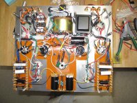
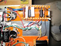
So, this is my messy cabinet inside. I put the switches out, and tried to clean a bit of mess, not very successful in the latter
Anyway in the second picture you see the audio stage of one channel. From the right you can see:
1) 6N1 Cathode leds (matched I have 3.438 V it both channels)
2) KT88 220K grid resistor
3) Coupling capacitor
4) 1K resistor to grid
5) Last block is the cathode resistor and capacitor (snubbed randomly with 1uF)
I was wondering if it's worth just to put the coupling capacitor between the two sockets, reducing signal path... I mean I don't have any noise.
Jeff, for the OPTs for the next project (300B) I think I will go for Japanese ones next project...I live in Tokyo.
Here I see that Japanese rate Tamura, then Tango and Hashimoto. Unfortunately Tango transformers hardly have 4 ohm tap, and my Sonus Faber are 4 ohm.
I also was thinking of assembling monoblocks, and I would like to have a power transformer with universal primary. (As I will go back to Europe in few years) In Japan it's just impossible to find power transformers with universal primary.
By the way, what tube to choose ? Any idea ?
Merry Christmas (or Emperor Birthday, in Japan)
Davide
Attachments
I have the switch for the cathode resistor installed. By the way, I calculated that in the worst case scenario the 3000K resistor has a dissipation of 0.8 W, so putting a 10 W is really not necessary. The 560 could go slightly over 5W if you drain 100 mA with the KT88, but maybe it's safer to keep it 10 W.
My amp has a voltage drop of 36.4v over the 470R resistor, so that gives me a dissipation of 2.82W (UL mode).
I figured the 10W resistor will stay cooler
So, this is my messy cabinet inside. I put the switches out, and tried to clean a bit of mess........
By the way, what tube to choose ? Any idea ?
What mess??? Looks great!
Where did you get those nice selector switches we see from the underside? I love the way they hook up.
As far as tubes go for the next project I am seriously thinking of spending extra on this project and going with a pair of tubes I have heard are simply the best.....supposedly better than WE. It is the KR 300B XLS here: KR Audio : KR 300BXLS : tubeAudioPRODUCTS.com
They are about twice as much as I was hoping to spend initially but I figure you only live once......
Check this amp out, I think I am going to try something like this for the next amp I build on a single chassis.....
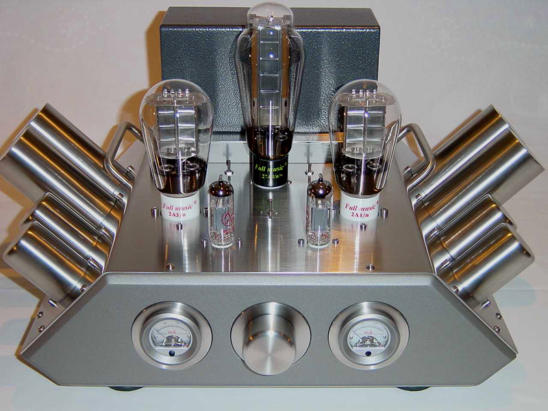
Kinda reminds me of a American big block V8!
Jeff
- Status
- This old topic is closed. If you want to reopen this topic, contact a moderator using the "Report Post" button.
- Home
- Amplifiers
- Tubes / Valves
- stereo SE kt88 build ... abdellah diyaudioprojects design