1. Is it better to use a shield instrument cable for the input signal wires from the RCA jack to the 100k Alps as shown?...
2. Should I use a separate shielded cable or wire for the neg RCA input terminal?
3. Where should I connect the shield around the cable to - RCA neg terminal, nothing, or RCA terminal star ground?...
1) better than not....yes.
2) I did simply because I had single wire within the shield. If you had double shielded wire that would be fine too. Both + and - are part of the signal path and are subject to interference.
3) I ground one end, generally closest to the chassis input, to the earth mains. I have excellent results using this technique.
I also use shielded cable from the Alps pot to the grid of the driver tube. Some may feel this is not needed but I figure the whole path is subject to interference. It doesn't take too much more to do this.
Jeff
Thanks, Jeff. Since I haven't placed the order from Parts Express yet, I do have the option of using a single (instrument, 1x20ga) cable or double shielded (mic, 2x22ga) cable from Parts Express.
Did you ground the shield from the pot to the grid driver input too?... If so, was it to the same ground share by the RCA input star ground?...
Thanks
Did you ground the shield from the pot to the grid driver input too?... If so, was it to the same ground share by the RCA input star ground?...
Thanks
Attachments
Shield grounding
Check this out before you buy your wire: 25' Mil Spec 20 AWG High-end Audio Silver Wire 600V - eBay (item 150390209617 end time Jan-17-10 12:00:12 PST)
I run small jumpers between each piece of shielded wire so in the end I have only one wire running from the end of one wire to the mains ground. So, yes I ground everything shielded.
Jeff
Thanks, Jeff. Since I haven't placed the order from Parts Express yet, I do have the option of using a single (instrument, 1x20ga) cable or double shielded (mic, 2x22ga) cable from Parts Express.
Did you ground the shield from the pot to the grid driver input too?... If so, was it to the same ground share by the RCA input star ground?...
Thanks
Check this out before you buy your wire: 25' Mil Spec 20 AWG High-end Audio Silver Wire 600V - eBay (item 150390209617 end time Jan-17-10 12:00:12 PST)
I run small jumpers between each piece of shielded wire so in the end I have only one wire running from the end of one wire to the mains ground. So, yes I ground everything shielded.
Jeff
Thanks, Jeff. That cable is fantastic! Good thing I didn't place the order @ P.E. Adding small jumpers connecting all the shielding is a great idea. This clears up the issue of low noise inputs.
Thanks again!
Thanks again!
because my b+ is a bit low [328 on the plate ] i was thinking to get a other transformer , now i found 1 second hand on the internet ,wich is very suitable
only it doesnot have 5 volt for the 5u4 ,it has 6,3 volt with 5 ampere
is it posible with a resistor to lower it for the 5u4 to 5 volts while the others tubes keep 6,3 v ? grtz ko
What is the voltage on your secondary? Maybe if you use 5ar4 rectifier tube with higher capacitance on the first C on the PSU, it might go up to around 370VDC which is quite acceptable for this circuit.
hello alexWhat is the voltage on your secondary? Maybe if you use 5ar4 rectifier tube with higher capacitance on the first C on the PSU, it might go up to around 370VDC which is quite acceptable for this circuit.
thanx for the advice ,i will try to get a 5ar4 , have 5 5u4 and 4 5u4gb in stock
the trafo is a amhro with 2 times 320 ac wich gives dc a 350 volt b+ by 200ma dc with 328 on the plate ,first c is 33uf 450v then 12h 400ma chocke the aerovox 220uf 600v c 150 ohm resistor second aerofox 220uf then b+ from b+ 2 times 15 k then 3 ,3 uf to ground continuing from the hot side of the 3,3 uf a 47k to the 6n1p ev ,no hum even with my philips ad5200m full range speakers with a 97db rendement grtz ko
Hi, what HT do you get on the driver with the led in place. If I set the cathode to 3.4 V I have the plate at 255 V. If I put only one led I get around 210 V. Only with a 300ohm resistor I manage to drain more current and get to 200 V. Is it normal ? I am worried as the maximum rating of the 6n1p is 250 V and I am always running higher.
By the way my B+ is around 390 V.
Regards,
Davide
By the way my B+ is around 390 V.
Regards,
Davide
For the 274BX Hammond Power Transformer (375-0-375), I measured the voltages across the two red secondary wires:
Red1-to-Gnd = 455VAC
Red2-to-Gnd = 460VAC
Red1-to-Red2 = 875VAC
QUESTION: How do I calculate the no load open voltage for PSUD2, do I divide 875VAC across the secondary wires by 2 to get 438VAC?...
If so, 438VAC seems way too high (additional caps will raise the voltages to 450V range). According to PSUD2 simulation, a 330R after C1 will bring the voltage down to 410VDC. But, I am not sure if placing a high value R in the PSU path is a good idea for dynamics and transient response?...
Should I use a 350-0-350 PTX instead. Any thoughts?...
BTW... I've NEVER worked with any circuit higher than 12VDC before - first time I've ever worked with high voltage circuits, let alone reading 875VAC on my meter!!! Needless to say I had 911 on speed-dial! First time I tried - my digital meter fried, even at the 1000VAC setting. My second reading was on my 20 year old Radio Shack analog meter and that worked flawlessly...
Attachments
Last edited:
hello alex
thanx for the advice ,i will try to get a 5ar4 , have 5 5u4 and 4 5u4gb in stock
the trafo is a amhro with 2 times 320 ac wich gives dc a 350 volt b+ by 200ma dc with 328 on the plate ,first c is 33uf 450v then 12h 400ma chocke the aerovox 220uf 600v c 150 ohm resistor second aerofox 220uf then b+ from b+ 2 times 15 k then 3 ,3 uf to ground continuing from the hot side of the 3,3 uf a 47k to the 6n1p ev ,no hum even with my philips ad5200m full range speakers with a 97db rendement grtz ko
What is the DCR of your choke?
I run a simulation on PSUD2, I assumed the DCR of your choke to be 150R, with the KT88 biased at around 70ma each and the 6n1p biased at 4ma each, your B+ should be around 383VDC, this should work very well with the circuit.
HTH.
Last edited:
88man,
Why would you calculate based on no load open voltages? Just use the estimated from the factory, it should be close enough. Using the open no load voltages on PSUD2 will not be an accurate estimation of what is going on in the circuit. I used a 375-0-375 and had 52uF before the choke and had my voltages spot on. Why are you putting the extra cap in front of the choke? That will only work to bring your final voltage higher, likely higher than needed. I would use no more than about 50-60uF before the choke, put the rest of your caps after it. The original design used between 10 and 40 before the choke depending on which website you found it. Again,
The no load open voltage is not where the circuit will be working with your 174mA load. It should be within a few % of the specs stated on the trafo.
Jeff
if you mesure high voltage , the golden rule is keep your left hand in your pocket when you do it , so when something goes wrong the voltage doesnot run over your heart circuit and you have a good change to surviveFor the 274BX Hammond Power Transformer (375-0-375), I measured the voltages across the two red secondary wires:
Red1-to-Gnd = 455VAC
Red2-to-Gnd = 460VAC
Red1-to-Red2 = 875VAC
QUESTION: How do I calculate the no load open voltage for PSUD2, do I divide 875VAC across the secondary wires by 2 to get 438VAC?...
If so, 438VAC seems way too high (additional caps will raise the voltages to 450V range). According to PSUD2 simulation, a 330R after C1 will bring the voltage down to 410VDC. But, I am not sure if placing a high value R in the PSU path is a good idea for dynamics and transient response?...
Should I use a 350-0-350 PTX instead. Any thoughts?...
BTW... I've NEVER worked with any circuit higher than 12VDC before - first time I've ever worked with high voltage circuits, let alone reading 875VAC on my meter!!! Needless to say I had 911 on speed-dial! First time I tried - my digital meter fried, even at the 1000VAC setting. My second reading was on my 20 year old Radio Shack analog meter and that worked flawlessly...
i used to work as high voltage electrician ,a other tip is to use bleeder resistors over your caps ,so that they slowly empty when the current is of
grtz ko
So I found out that my amplifier behaves in different way if I attach to it my Iphone or a proper preamplifier.
If the Denon 4308 is attached the driver drains the correct current and the HT voltage goes to 190 V, if the Iphone (on batteries) is attached the HT of the driver stays at 250 V.
Guess it was not such a good idea to put absolutely nothing (no potenziometer, no 1 Mohm resistor to ground)
Additionally, due to tolerances of components values of voltages are slightly different for left and right. What would you fine tune to have it completely symmetric ?
I was thinking to do the following, having a trimmer on the cathode resistor of the KT88 and work on the plate resistor of the driver to have the same HT for both channels. Now I have 8 V difference between R and L on the driver HT and 0.something for the KT88 cathode. The cathode of the driver stays at 3.4, because of the diodes.
Best Regards,
Davide
I guess I have to go back to study a bit :-(
I connected a potentiometer between the sources and the driver:
a) With the iphone turning the potentiometer was changing the HT value of the driver, or better his current drain.
b) with the preamplifier there was no change.
I guess this is because different source impedance.
Best Regards,
Davide
I connected a potentiometer between the sources and the driver:
a) With the iphone turning the potentiometer was changing the HT value of the driver, or better his current drain.
b) with the preamplifier there was no change.
I guess this is because different source impedance.
Best Regards,
Davide
Thanks Jeff and Seel34 for the advice!
I was never taught how I should use PSUD2. I've been trying to figure it out on my own. Based on what others were getting, I quantitatively deducted that the "no load voltage" to be around 398V on a 375V PTX. I began to question myself, and decided to measure the this "no load voltage" on the actual transformer, thinking that's a direct method. Thanks, Jeff for explaining how I should be using PSUD2. I'll keep it as a 100% simulation.
I just ran the program again, and entered 375V and 0.175A, and I now realize that PSUD2 calculates the "no load voltage" at 393V. Hope that sounds right?...
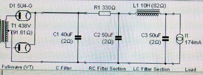
By the way, I originally was simulating a CLCRC filter, then there was discussion of ripple being better in CRCLC configuration - that's why I had 2 caps before the inductor. Oh well...
I hope I did things right - here are the simulations I am getting for my PSU:
375V PTX (393V) - 5U4G - 40uF - 10H - 50uF - 50uF
V=406, Ripple=0.034V
I can live with 406V for B+ without any R in the KT88 path. Here are simulations for the RC filters for the 6N1P based on several builders:
375V PTX (393V) - 5U4G - 40uF - 10H - 50uF - 50uF(160ma tap) - 100R - 10uF(5ma tap)
V=410, Ripple=0.025V (@ 6N1P)
375V PTX (393V) - 5U4G - 40uF - 10H - 50u - 50uF(160ma tap) - 100R - 15uF(5ma tap)
V=410, Ripple=0.020V (@ 6N1P)
375V PTX (393V) - 5U4G - 40uF - 10H - 50uF - 50uF(160ma tap) - 240R - 10uF(5ma tap)
V=409, Ripple=0.015V (@ 6N1P)
375V PTX (393V) - 5U4G - 40uF - 10H - 50uF - 50uF(160ma tap) - 240R - 15uF(5ma tap)
V=409, Ripple=0.0011V (@ 6N1P)
375V PTX (393V) - 5U4G - 40uF - 10H - 50uF - 50uF(160ma tap) - 240R - 47uF(5ma tap)
V=409, Ripple=0.0039V (@ 6N1P)
For the driver input RC filter, I'll use Solen 630V PP caps. If I go with 10uF in RC filter, I'll use (2) caps. If I go with 15uF or 47uF caps in RC filter, then I'll use (1) cap shared by both inputs of 6N1P.
I was never taught how I should use PSUD2. I've been trying to figure it out on my own. Based on what others were getting, I quantitatively deducted that the "no load voltage" to be around 398V on a 375V PTX. I began to question myself, and decided to measure the this "no load voltage" on the actual transformer, thinking that's a direct method. Thanks, Jeff for explaining how I should be using PSUD2. I'll keep it as a 100% simulation.
I just ran the program again, and entered 375V and 0.175A, and I now realize that PSUD2 calculates the "no load voltage" at 393V. Hope that sounds right?...
By the way, I originally was simulating a CLCRC filter, then there was discussion of ripple being better in CRCLC configuration - that's why I had 2 caps before the inductor. Oh well...
I hope I did things right - here are the simulations I am getting for my PSU:
375V PTX (393V) - 5U4G - 40uF - 10H - 50uF - 50uF
V=406, Ripple=0.034V
I can live with 406V for B+ without any R in the KT88 path. Here are simulations for the RC filters for the 6N1P based on several builders:
375V PTX (393V) - 5U4G - 40uF - 10H - 50uF - 50uF(160ma tap) - 100R - 10uF(5ma tap)
V=410, Ripple=0.025V (@ 6N1P)
375V PTX (393V) - 5U4G - 40uF - 10H - 50u - 50uF(160ma tap) - 100R - 15uF(5ma tap)
V=410, Ripple=0.020V (@ 6N1P)
375V PTX (393V) - 5U4G - 40uF - 10H - 50uF - 50uF(160ma tap) - 240R - 10uF(5ma tap)
V=409, Ripple=0.015V (@ 6N1P)
375V PTX (393V) - 5U4G - 40uF - 10H - 50uF - 50uF(160ma tap) - 240R - 15uF(5ma tap)
V=409, Ripple=0.0011V (@ 6N1P)
375V PTX (393V) - 5U4G - 40uF - 10H - 50uF - 50uF(160ma tap) - 240R - 47uF(5ma tap)
V=409, Ripple=0.0039V (@ 6N1P)
For the driver input RC filter, I'll use Solen 630V PP caps. If I go with 10uF in RC filter, I'll use (2) caps. If I go with 15uF or 47uF caps in RC filter, then I'll use (1) cap shared by both inputs of 6N1P.
Question:
What's more important, decrease the ripple on the output tube, or on the driver? Sure, if you can do both is better, just curious what contributes more to the hum in the output.
BR,
Davide
What's more important, decrease the ripple on the output tube, or on the driver? Sure, if you can do both is better, just curious what contributes more to the hum in the output.
BR,
Davide
how do you correctly measure the currents and voltages in a tube amp and on wich points ??
i am not sure what is the correct way of mesuring all values,i also was reading the mail from davide on the subject , the way i measure is with boxes conected ,pasieve pre conected and playing low volume music ,if i measure with out everything conected my the voltage is higher ,with a resistor on the 6n1p the plate current on the el34 is also higher then with the leds ,a ecc88[6dj8]
gives also a differents in the voltage on the el34, so who can explane how and on wich points correctly to measure this amp . thank you in advance
grtz ko
ps alex ik think my choke is 138 ohm resistance
pps wich psu program are you using ?
What's more important, decrease the ripple on the output tube, or on the driver? Sure, if you can do both is better, just curious what contributes more to the hum in the output.
The driver is more critical to ripple, noise, and hum than the output tube. That's why I am using shielded cable for the input connections and the additional RC filter stage for the 6N1P.
dividing
Hi all,
I built this amp 6 months ago, I'm very happy with it.
A friend suggested a lot of mod, and I tried almost all of them.
Has someone tried to divide the B+ just after the first common CRC?
Or used 2 power tranny?
I used LC and fast recovery diodes trying have a sort of separation of the 2 channel. Think is sound improving.
Happy new year
V.
Last edited:
Diodes
I have given some consideration to this idea but I have never actually heard of it being done. Seems to me if you place a diode on the B+ after the split that would help reduce crosstalk through the power rail......at least that is what I have theorized until now. How exactly did you place the diode? Did you also bypass the diode with a cap? I have a few fast recovery diodes laying around and was thinking to place at least 2 in parallel on each power rail after the last cap in my circuit. Is there anywhere you know of where I could read more about this approach?
Thanks,
Jeff
I used LC and fast recovery diodes trying have a sort of separation of the 2 channel.
I have given some consideration to this idea but I have never actually heard of it being done. Seems to me if you place a diode on the B+ after the split that would help reduce crosstalk through the power rail......at least that is what I have theorized until now. How exactly did you place the diode? Did you also bypass the diode with a cap? I have a few fast recovery diodes laying around and was thinking to place at least 2 in parallel on each power rail after the last cap in my circuit. Is there anywhere you know of where I could read more about this approach?
Thanks,
Jeff
Hi Jeff,
I don't know if others have tried. As I wrote before it was a friend of mine to suggest that mod. I will ask.
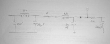
If I remember right (I'm not at home to check if I'm right) the schem was that you can see in the attached file.
excuses for the quality, it's the best I can do from here 🙂
the A point is the splitting channel point. The B point is where you split B+ to go to OPT. then you have the part with the RC 10k / 100uF where you go to the driver. It was suggested to me to use schottky diodes, but I couldn't find them here.
The last 10k/100uF will soon be replaced to LC 5H/100uF to try how it sounds.
The load on the driver is now 37K, with the LC will be 47K as per original specs.
Hope you can understand my poor english,
Vincenzo
I don't know if others have tried. As I wrote before it was a friend of mine to suggest that mod. I will ask.
If I remember right (I'm not at home to check if I'm right) the schem was that you can see in the attached file.
excuses for the quality, it's the best I can do from here 🙂
the A point is the splitting channel point. The B point is where you split B+ to go to OPT. then you have the part with the RC 10k / 100uF where you go to the driver. It was suggested to me to use schottky diodes, but I couldn't find them here.
The last 10k/100uF will soon be replaced to LC 5H/100uF to try how it sounds.
The load on the driver is now 37K, with the LC will be 47K as per original specs.
Hope you can understand my poor english,
Vincenzo
Attachments
- Status
- Not open for further replies.
- Home
- Amplifiers
- Tubes / Valves
- stereo SE kt88 build ... abdellah diyaudioprojects design