Jeff,
I don't have a volume potentiometer at all :-(.
I use now only film capacitors, I only have electrolitics on the cathodes of the kt88.
Could you measure the hum you have in the speakers with an AC voltmeter, because my feeling is that I am getting paranoyd about something really minor. I know that it is there, I can barely hear it when the amp is silent, but it is the only thing I am listening too (probably).
I tried various combination of valves and it looks like some are more noisy than others. Again as I don't have experience with these components, I am not sure what is the tolerance. Let's say one EL34 gives me 3 mV of hum, the other 5mV (swapping on the same channel). Is it normal? Shall I ask for replacement?
Thanks,
Davide
P.S.: Jeff. do you need the switches ?
Yes, but you should best parallel a 1K resistor to the cathode resistor of theHi,
Is it possible to substitute the 6n1p with a 6922? I just worry if the 6922 may not withstand the high voltages but i've got lots of 6922s. Thanks.
6DJ8/6922 to bring the operating point right. I have done this with and without 500R on the cathode and it sounds much better with the 500R on the cathode. This is addressed somewhere at the very begining of the thread on the first 1-2 pages I think.
Jeff
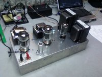
Finally finished!
I finally received my OPTs from Hong Kong and finished my KT88 SE amp.
The sound is absolutely fanastic! I have zero hum or noise and I am using an AC filament supply. The ripple on my B+ measures 21 mV. The only thing I may be concerned about is that my B+ measures 430V, although the other voltages measure about right.
I have 399V on the KT88 plates and 39.3V on pin 8 of the KT88s. KT88 current calculated at 75mA.
I have 221V after the LC filter to the 6N1P, 206V on the 6N1P plate after the 47K, and 4.38V on pin 3 & 8 on the 6N1Ps.
I used a 1.2K for the SG resistor in UL mode and 100R for triode mode. I used a 330K from KT88 plate to 6N1P plate for feedback that can be switched in or out. From preliminary listening tests, switching in feedback seems to clean up a bit of distortion when running UL mode at full throttle.
My power supply filters are a 30uF Ampohm polypropolene for the first cap and 4 - 100uF Nichicon PT electrolytics in series-parallel, with balancing resistors to achieve a 100uF 750V cap for the second. I used the 5U4GB rectifier.
My cathode setup is 560R Caddock power film, 220uF Elna Silmic for KT88s, and 1K metal film, 100uF Elna Silmic for the 6N1P.
I could not be happier with the way this amp sounds. I am really liking the triode mode so far, seems very open and dynamic. This amp has excellent low-end response as well as a very clear high-end. My next step is to complete my 98dB 2-way speakers. The speakers I am using now are the Leach Vifa 2-way DIY, around 89dB and they sound really nice.
What do you all think about the 430V B+? Don't fix it if it's not broken?
Thanks to everyone on this site for the invaluable information that allowed this project to be a success!
Attachments
Congratulations for your new build !!
Just curious: when you say "zero hum" do you mean 0 mV measured with a votmeter ? In case, could you kindly attach a voltmeter to the speakers output when the system is idle (better if you connect a small resistor between + and - of the signal).
I am tuning my amp, trying to make it as silent as possible, I need a comparison to understand where to stop, it's my first build.
Thanks,
Davide
Looks great (will look even better with the wood if I ever get it done!!!). Congrats!
This is a fine sounding amp isn't it. I am still tickled to turn mine on every time I get too.
Jeff
This is a fine sounding amp isn't it. I am still tickled to turn mine on every time I get too.
Jeff
Congrats on the completion of your amp!
It does looks very neat and nice. I would hope that I can achieve hum-free for mine when I redo some of the wiring this weekend 🙂
It does looks very neat and nice. I would hope that I can achieve hum-free for mine when I redo some of the wiring this weekend 🙂

Just curious to ask, did anyone connected pin 9 of the driver ?
Cjctan, could you kindly explain me what are the two diodes and resistor in the ground bus? It's not the first time I see it, and I am curious to understand.
Best Regards,
Davide
Cjctan, could you kindly explain me what are the two diodes and resistor in the ground bus? It's not the first time I see it, and I am curious to understand.
Best Regards,
Davide
Hi Davide,
The voltage across the speaker terminals is 0.7mV at idle.
Scott
The voltage across the speaker terminals is 0.7mV at idle.
Scott
Congratulations for your new build !!
Just curious: when you say "zero hum" do you mean 0 mV measured with a votmeter ? In case, could you kindly attach a voltmeter to the speakers output when the system is idle (better if you connect a small resistor between + and - of the signal).
I am tuning my amp, trying to make it as silent as possible, I need a comparison to understand where to stop, it's my first build.
Thanks,
Davide
Just curious to ask, did anyone connected pin 9 of the driver ?
Cjctan, could you kindly explain me what are the two diodes and resistor in the ground bus? It's not the first time I see it, and I am curious to understand.
Best Regards,
Davide
For me, I connect the pin 9 of 6n1p to the chassis ground. Not sure whether this is the best way.
I have read a post from a forumer here that this way is better to tied the signal ground to the earth from the AC mains to minimize ground noise.
Perhaps some experts can fill us in with better insights
Davide,
I connected pin 9 of the 6N1P to ground.
I connected pin 9 of the 6N1P to ground.
Just curious to ask, did anyone connected pin 9 of the driver ?
Cjctan, could you kindly explain me what are the two diodes and resistor in the ground bus? It's not the first time I see it, and I am curious to understand.
Best Regards,
Davide

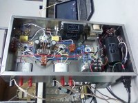
Updates....
Managed to eliminate the nasty humming at the outputs that I experienced last weekend. I have rewired the heaters connections by running them at the chassis plate and also tightly twisted them but to no avail. The humming still as loud as previously.
I managed to do some probing with an old oscilloscope that I borrowed and was surprised to see ~1.4V of ripple on the B+ supply rail !!!!
The original configuration of the B+ was as folows
Trans --> 5AR4 (with UF4007) --> 470nF --> 10H --> 100uF + 68uF + 0.1uf (all MKP)
After trying out a few filtering configuration, I have settled on the following configuration. I wanted to use "e-cap-less" for the B+ but couldn't due to lack of space and POOR layout initially.
Trans --> 5AR4 (with UF4007) -->680nF --> 10H --> 150+150uF Mundorf MLytic HV cap --> 5H --> 100uF + 0.1uF (MKP ) **A** --> 270 ohm kiwame resistor --> 68uF (MKP) **B**
**A** : To Output Transformers (Noise ripple ~ 10mV )
**B** : To 6N1P
Currently enjoying it with a pair of Mullard (New Sensor) EL-34 🙂
Ctctan,
I think the value of the first C filter is off. Here everybody has something between 10uF and 40uF. Be careful what rectifier you use, as some of them have a very small limit for the first C. If you put 10 you will be safe in any condition.
D.
I think the value of the first C filter is off. Here everybody has something between 10uF and 40uF. Be careful what rectifier you use, as some of them have a very small limit for the first C. If you put 10 you will be safe in any condition.
D.
Ctctan,
I think the value of the first C filter is off. Here everybody has something between 10uF and 40uF. Be careful what rectifier you use, as some of them have a very small limit for the first C. If you put 10 you will be safe in any condition.
D.
Hi Davide,
I am using choke input filtering aka LC filter for the first stage and not CLC. The small capacitor (680nF currently) is for smoothing the switching noise of the rectifier (this was recommended by an expert in this forum ).
Thanks for highlighting this issue.
I would wonder if with the way you have built a bridge with the combo of diodes and tube rectification if the rule of the first cap value even applies? Also, with adding caps to eliminate switching noise I generally use a small value cap across both ends of the diode, in parallel with the diode.
I would wonder if with the way you have built a bridge with the combo of diodes and tube rectification if the rule of the first cap value even applies? Also, with adding caps to eliminate switching noise I generally use a small value cap across both ends of the diode, in parallel with the diode.
Hi Jeff,
I had a hard time of searching for more information or the best approach when I want to try the hybrid tube rectification. I understand your recommendation on "bypassing" the SS diodes. I will will try out soon.
This is thread where I first asked abt the hybrid tube rectification....
http://www.diyaudio.com/forums/tubes-valves/140179-question-hybrid-bridge-using-5ar4.html
Power Supply
A comment on the power supply configuration. No need to make it complicated. My configuration is: Hammond 374BX-5U4GB-30uF polypropylene-Hammond 193J-100uF electrolytic, with AC filaments, and I have no hum or noise. I increased the voltage handling capacity of the 100uF/450V caps by using 4 in a series-parallel configuration. I took the high voltage from the 5V center tap. This is the recommended connection for the 5U4GB if a 5V center tap is available. It is important to make the high voltage center tap to the first capacitor ground as an independent connection to the star ground. After the output of the 193J choke to the second capacitor (100uF), make that ground another independent connection to the star ground. It is also important to connect the filament center tap directly to the star ground.
Hope this helps.
My initial B+ filtering implementation was fairly simple with choke-input filtering. However the ripple on the B+ rail was ~1.4V. Maybe my selection of the make of choke and film caps are not effective in the filtering. This results in the humming that I was getting.
I also reference the filament winding to the star ground through 2 100R resistors.
When I plug the values you are using into PSUD2 it shows that you are only getting about 283V at your **A** point, assuming you are using a 375-0-375 power transformer. Is this correct? If you were to make the first cap (or add) at least 10uF it would bring your B+ up to about 398V.
I missed the fact initially that you were using the 5AR4. With the 5AR4 the simulation shows 305V. A 5uF as the first cap would bring you to 414V.
Last edited:
- Status
- Not open for further replies.
- Home
- Amplifiers
- Tubes / Valves
- stereo SE kt88 build ... abdellah diyaudioprojects design