When I plug the values you are using into PSUD2 it shows that you are only getting about 283V at your **A** point, assuming you are using a 375-0-375 power transformer. Is this correct? If you were to make the first cap (or add) at least 10uF it would bring your B+ up to about 398V.
I missed the fact initially that you were using the 5AR4. With the 5AR4 the simulation shows 305V. A 5uF as the first cap would bring you to 414V.
The measured voltage after the 193J (10H) is ~410V and 395V at point **A** which very close to the simulated value in PSUD2.
I am using a custom wound power trans with a 480VAC winding tap (no center-tapping)
Hi guys,
As I was not really satisfied of the result of my first build, and I wanted to make some more experiments I disassemble everything and I build some modules on plastic boards, so it was easy and almost safe to do experiments.
Now I have the following modules:
1) Channels component (one for each channel)
2) OPT (one for each channel)
3) power transformer
4) PSU filter
Additionally I have various DC modules for the filaments, regulated and unregulated.
The aim of this is to test many configurations without the restrain of the chassis, work on reducing the final size of the modules and of the final assembly, reduce the signal path.
I found some amazing connectors rated 500 V for the interconnection of the modules.
Following my finding (Maybe are not news for most of you)
HUM
There are mainly two sources of hum, the ripple on the B+ and the grounding issues. Please note that the amplifier is spread on my table, so no enclosure.
Feeding the filaments with DC has effect on the hum, only because has an effect on the grounding, if the latter is not done properly.
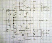
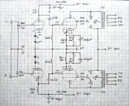
The configuration of the PSU that I performed better for the noise for me is the following:
5R4WGB-22uF-10H(81ohm)-200uF-tap-200ohm-47uF
The 200uF and 47uF capacitor are Film mylar capacitor.
This gives me a hum less than 1mV (With a 1000K resistor on the input)
I am using this rectifier as my transformer stays a bit high on the voltage.
I also corrected a bit the resistance of my secondary that is a bit low adding two 50ohm resistors. This should limit the rush current, protect the rectifier (i got a flash once) and sound a bit better. I don't want to exaggerate, as it is like putting a heater in the chassis.
Reducing the first capacitor to 10uF increase the hum, increasing it does not reduce it.
Additionally going over 40uF you have limitations on the rectifiers you can use.
The choice of the type of the first capacitor is not so critical, I tried the solen and replaced with an electrolytic, without measurable and audible effect
Replacing the 200 ohm resistor with a second choke does not have big effect. Also increasing the value of the 47uF to 100uF had very little effect.
With this configuration you can also see in PSU2 that the psu comes up very smoothly and does not bounce around when the load change.
It is important to put the second RC filter (I used only one for both the drivers) it brought the hum down of 1.5 mV although I measure an higher ripple compared to what is foreseen in PSU2.
For the grounding I started having one wire to the start for each point and I arrived to the following configuration:
For the PSU the first cap is directly connected to the center tap of the transformer (also like this it is easy to mount it mechanically. The other two capacitors are connected in a bus and then to the star. The earth of the primary also goes to the star.
I run a bus with a thick copper wire (so it stands by himself) around the components. All the components that go to ground are soldered to the copper wire. Actually I did not use any wire to solder the components, they are attached directly to the sockets. The wires only run from the tube board to the opt.
the most important thing is the pin n9 of the driver. Connect this to ground and you will cut most of the hum problems.
I tried the unregulated DC modules 4700uF-0.1ohm-4700uF. Under load there is still a ripple of 1.8V. Increasing the capacity to 10000uF does not change much. Additionally be careful as the rectifiers get very hot.
With the regulator I had 20mV of ripple. Tried to connect to both the tubes, only to the driver, use separate, but no changes. I also tried something I saw in the simple se by tubelab. From what I understood he polarize the hearers with a DC voltage similar to the cathode. I am not sure I understand why (I have some ideas, but I don't want to say something too stupid), but, at least on the hum, it does not have any effect.
Results, now I am able to mount tubes, switches and opt and connectors on a board 10X15cm (I am using James transformers).
I am still working on making the psu smaller, but here it gets hard, as the 200uF cap has a 62mm of diameter, the transformer (I am thinking of using another one for the final build) is a beast 120x110 mm rated 280mA. Too much !
I was thinking about monoblocks, but I cannot find a small transformer rated around 90mA.
Hope this will help someone.
DON'T FORGET PIN 9 !!!
Goodnight,
Davide
As I was not really satisfied of the result of my first build, and I wanted to make some more experiments I disassemble everything and I build some modules on plastic boards, so it was easy and almost safe to do experiments.
Now I have the following modules:
1) Channels component (one for each channel)
2) OPT (one for each channel)
3) power transformer
4) PSU filter
Additionally I have various DC modules for the filaments, regulated and unregulated.
The aim of this is to test many configurations without the restrain of the chassis, work on reducing the final size of the modules and of the final assembly, reduce the signal path.
I found some amazing connectors rated 500 V for the interconnection of the modules.
Following my finding (Maybe are not news for most of you)
HUM
There are mainly two sources of hum, the ripple on the B+ and the grounding issues. Please note that the amplifier is spread on my table, so no enclosure.
Feeding the filaments with DC has effect on the hum, only because has an effect on the grounding, if the latter is not done properly.
The configuration of the PSU that I performed better for the noise for me is the following:
5R4WGB-22uF-10H(81ohm)-200uF-tap-200ohm-47uF
The 200uF and 47uF capacitor are Film mylar capacitor.
This gives me a hum less than 1mV (With a 1000K resistor on the input)
I am using this rectifier as my transformer stays a bit high on the voltage.
I also corrected a bit the resistance of my secondary that is a bit low adding two 50ohm resistors. This should limit the rush current, protect the rectifier (i got a flash once) and sound a bit better. I don't want to exaggerate, as it is like putting a heater in the chassis.
Reducing the first capacitor to 10uF increase the hum, increasing it does not reduce it.
Additionally going over 40uF you have limitations on the rectifiers you can use.
The choice of the type of the first capacitor is not so critical, I tried the solen and replaced with an electrolytic, without measurable and audible effect
Replacing the 200 ohm resistor with a second choke does not have big effect. Also increasing the value of the 47uF to 100uF had very little effect.
With this configuration you can also see in PSU2 that the psu comes up very smoothly and does not bounce around when the load change.
It is important to put the second RC filter (I used only one for both the drivers) it brought the hum down of 1.5 mV although I measure an higher ripple compared to what is foreseen in PSU2.
For the grounding I started having one wire to the start for each point and I arrived to the following configuration:
For the PSU the first cap is directly connected to the center tap of the transformer (also like this it is easy to mount it mechanically. The other two capacitors are connected in a bus and then to the star. The earth of the primary also goes to the star.
I run a bus with a thick copper wire (so it stands by himself) around the components. All the components that go to ground are soldered to the copper wire. Actually I did not use any wire to solder the components, they are attached directly to the sockets. The wires only run from the tube board to the opt.
the most important thing is the pin n9 of the driver. Connect this to ground and you will cut most of the hum problems.
I tried the unregulated DC modules 4700uF-0.1ohm-4700uF. Under load there is still a ripple of 1.8V. Increasing the capacity to 10000uF does not change much. Additionally be careful as the rectifiers get very hot.
With the regulator I had 20mV of ripple. Tried to connect to both the tubes, only to the driver, use separate, but no changes. I also tried something I saw in the simple se by tubelab. From what I understood he polarize the hearers with a DC voltage similar to the cathode. I am not sure I understand why (I have some ideas, but I don't want to say something too stupid), but, at least on the hum, it does not have any effect.
Results, now I am able to mount tubes, switches and opt and connectors on a board 10X15cm (I am using James transformers).
I am still working on making the psu smaller, but here it gets hard, as the 200uF cap has a 62mm of diameter, the transformer (I am thinking of using another one for the final build) is a beast 120x110 mm rated 280mA. Too much !
I was thinking about monoblocks, but I cannot find a small transformer rated around 90mA.
Hope this will help someone.
DON'T FORGET PIN 9 !!!
Goodnight,
Davide
Davide,
So I take it you are still having some hum problems? Or not?
I wanted to mention something Morgan Jones writes about when it comes to grounding and buses. There are differential currents trough the bus at different points so it is imortant not to connect your grounds to the bus in a way where the higher current grounds are downstrem from the lower current ones. i.e., bad idea to have the driver grounds connected close to the center tap of the transformer on the bus and then have the power tube grounds further down the bus.
I try to place the power tube ground right at the first capacitor ground on the bus then place each additional grounding in order of current down the bus going from highest to lowest. A star is of course optimal not often difficult to implement.
Davide, try Edcor for your power transformer needs. Tell Phyllis exactly what you are looking for and she will give you some recommendations of what they have that might work for your application. Edcor does have several designs that are not advertised on their website. These are custom designs others had built but are not listed. I have found they frequently have exactly what I need that another customer already paid the custom design fee for.
Jeff
I think now I am satisfied with the hum, less than 1mV is ok. My multimeter shows 0.2 mV when the amp is off.
I had a perfect star in the first build, but it did not help much.
Another thing that I forgot to mention is that I tried also the effect of center tappinf the filament AC with two resistor, or with a potentiometer, but did not see any measurable effect on the hum.
And also the grounding of the opt secondary does not change it (although you had different experience).
BR,
Davide
By the way, I measured the current from pin 9 of the driver, and it is around 7 mA. So now the My bus is:
star-KT88 cathode- pin 9 - driver cathode- kt88 grid - driver grid.
I tried to see if I could reduce the current from pin 9 playing with a potentiometer, but nothing.
Davide
star-KT88 cathode- pin 9 - driver cathode- kt88 grid - driver grid.
I tried to see if I could reduce the current from pin 9 playing with a potentiometer, but nothing.
Davide
I think now I am satisfied with the hum, less than 1mV is ok. My multimeter shows 0.2 mV when the amp is off.
I had a perfect star in the first build, but it did not help much.
Another thing that I forgot to mention is that I tried also the effect of center tappinf the filament AC with two resistor, or with a potentiometer, but did not see any measurable effect on the hum.
And also the grounding of the opt secondary does not change it (although you had different experience).
BR,
Davide
Can you hear the hum from your speakers?
Well, if I put my hear inside them maybe, but in normal life the noise from the refrigerator next room is much more audible.
D.
D.
I'm not sure what I'm missing here, but why would there be any current flow from the pin 9 internal shield of the driver?
By the way, I measured the current from pin 9 of the driver, and it is around 7 mA. So now the My bus is:
star-KT88 cathode- pin 9 - driver cathode- kt88 grid - driver grid.
I tried to see if I could reduce the current from pin 9 playing with a potentiometer, but nothing.
Davide
By the way, I measured the current from pin 9 of the driver, and it is around 7 mA. So now the My bus is:
star-KT88 cathode- pin 9 - driver cathode- kt88 grid - driver grid.
I tried to see if I could reduce the current from pin 9 playing with a potentiometer, but nothing.
Davide
Hi Davide,
I am really impressed by your efforts in the extensive experiments and measurements.
May I also ask the reason on your measurement of the Pin 9 of the driver?
So far also tried a few experiments on the B+ filtering. I cannot hear any humming even there is ~100mV (pk-pk) on the B+
I am pairing this amp with a pair of DIY Hempacoustics FR8C and I place my ear (not calibrated though 😉 ) in front of the drivers. Only the left drover have a very very faint humming as I guessed it is due to placement issue of the transformers
May I ask the opinions from you guys on the mode of operation for this amp? Is there such thing as certain output tubes is best for 1 operation mode (pentode/UL/triode) ?
So far I only used 1 pair of Mullard EL-34 and Tung Sol 6L6GC-STR (both made by New Sensor). For EL-34, I liked the Triode mode best as it sounded more balance throughout. The UL have more output power and sounded more dynamic but it seems a bit "shouty" at the highs to me.
As for the 6L6, I am very disappointed as all 3 modes sounded very lifeless esp the lows seems to be non-existence.
Are my findings close to you guys who have spent much more time with this amp design than me?
Presently, I only bought cheaper new production tubes as this is my first power amp built and I can afford to risk with expensive tubes. Now the amp is stable, I would appreciate if anyone can share with me what other tubes (affordable) are suitable for this amp design.
I agree, 6L6 family tubes don't sound good in tis amp. Too mushy or mellow, they lack high frequency response in my opinion.
I don't have any vintage tubes to run in this amp, so my favorite tubes are the EH 6CA7 big bottles in UL mode. I have to admit that I also like pentode mode with these tubes (as well as regular EH EL34's) even though the distortion is slightly higher. Could be that it's because I listen to classic rock mostly and the little bit of extra power helps.
Glenn
[edit] What's the deal with pin 9 of the driver being connected to ground?
I haven't done this on my amp and I don't have any noise issue. Just curious.
Last edited:
I am using electro-harmonix KT88s partially for cost reasons, ($60USD matched pair), mostly for reviews I've read. I had a few 6N1P-EV NOS rocket logo tubes leftover from a guitar amp I built a while ago, so I used one of those for the driver. I am using the electro-harmonix 5U4GB for the rectifier. I consider myself to have a pretty good ear, I've been playing guitar for 35 years and have been exposed to many, many hi-fi/pa systems over the years. My hearing has always and still does have an excellent frequency response.
I probably will try other tubes in the future, however I'm not sure how this amp could sound much better than it does. Very balanced from way low to high. I have no complaints whatsoever about the bass response. Very deep, very tight. The mids are there, and the highs magical.
I agree, I like the triode mode the best dynamics wise, but there is nothing wrong with ultralinear for that extra gain. I have stated this before, I included the ability to switch in feedback and while it does reduce distortion when running full-throttle, it takes a little away from the overall presence. I would like to add that in triode mode I have no apparent distortion audibly or when checked with my scope.
Last edited:
Thank you Glenn and Scott for your inputs
I will go for a tube shopping trip this coming weekend and seem like "bigger" or "fatter" tubes might be a better choice for this amp design 😀
Scott:
Does the feedback path only applies to UL mode? Is it safe to leave it there in the 2 other modes?
I will go for a tube shopping trip this coming weekend and seem like "bigger" or "fatter" tubes might be a better choice for this amp design 😀
Scott:
Does the feedback path only applies to UL mode? Is it safe to leave it there in the 2 other modes?
First DIY build: SET KT88 Amplifier
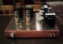
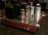
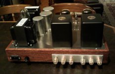
The externals of the amp are finally assembled, the red oak stained with rosewood finish, all terminals, switches, and tubes mounted, and the chassis work is completed, transformers have rubber grommet washers between the chassis plate and their bolts to eliminate any potential electromechanical coupling. For the RC filter (one for each channel) before the 6N1P plate, I bought parts for 10, 15, 47uF caps and 100R, 240R (2W). I am going with be using 10uF + 240R/2w.
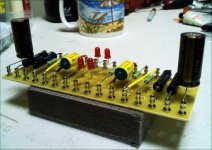
As you can see, the tag board is ready to go, but I am holding off on soldering the final tag board - I am deciding on which design to use.
Tag board 1:
-with 330k feedback resistor between KT88 and 6N1P plates
-with 1k series KT88 grid input resistor
-with 1M 6N1P input resistor to ground
-OR-
Tag board 2:
-NO 330k feedback resistor between KT88 and 6N1P plates
-NO 1k series KT88 grid input resistor
-NO 1M 6N1P input resistor to ground
Questions:
1. Which tag board/schematic will yield better sonics?
2. Will it matter what combination of RC I'll use for the filter?
Thanks guys, I could really use your advice since this is my first DIY project.
The externals of the amp are finally assembled, the red oak stained with rosewood finish, all terminals, switches, and tubes mounted, and the chassis work is completed, transformers have rubber grommet washers between the chassis plate and their bolts to eliminate any potential electromechanical coupling. For the RC filter (one for each channel) before the 6N1P plate, I bought parts for 10, 15, 47uF caps and 100R, 240R (2W). I am going with be using 10uF + 240R/2w.
As you can see, the tag board is ready to go, but I am holding off on soldering the final tag board - I am deciding on which design to use.
Tag board 1:
-with 330k feedback resistor between KT88 and 6N1P plates
-with 1k series KT88 grid input resistor
-with 1M 6N1P input resistor to ground
-OR-
Tag board 2:
-NO 330k feedback resistor between KT88 and 6N1P plates
-NO 1k series KT88 grid input resistor
-NO 1M 6N1P input resistor to ground
Questions:
1. Which tag board/schematic will yield better sonics?
2. Will it matter what combination of RC I'll use for the filter?
Thanks guys, I could really use your advice since this is my first DIY project.
Attachments
Last edited:
88man,
Your build looks very, very nice. Excellent craftsmanship. I would use the 1K grid input resistor on the KT88s. I did not use the 1M to GND for the driver, but I did not use a volume control on the amp. I used 100K to GND for the inputs. As far as the feedback goes, I would probably not bother with it if I was to build again as I think it takes away from the overall sonics of the amp. You could always add a DPDT and switch it in or out to see what you think. I used an LC filter (5H+10uf) for each driver channel. If you are going with RC it appears that most use the 250R+10uf circuit.
Scott
Last edited:
Thank you Glenn and Scott for your inputs
I will go for a tube shopping trip this coming weekend and seem like "bigger" or "fatter" tubes might be a better choice for this amp design 😀
Scott:
Does the feedback path only applies to UL mode? Is it safe to leave it there in the 2 other modes?
If you try feedback on this amp I would make sure you can switch it in or out. It only seems to clear up a bit of distortion in the UL mode when running wide open.
Thank you, Scott! Honestly, this project is a first for me in many respects... It is my first attempt at woodworking and tube circuits. For 5 months, I've been reading about woodworking, and DIY tube electronics online, and proper staining by reading Minwax brochures. Not bad for Jerry's kids, huh? 🙂
I had a Craftsman table saw which I had in the box for 2 years, thinking that I was going to build speakers... Well, the Scanspeak drivers, and Mundorf MK Supremes are still in the box, but at least I used the table saw for the first time by making my first miter cuts on this project.
There is no substitute for real experience so I thank you for the advice! I can FINALLY put it all together.
Hi Davide,
I am really impressed by your efforts in the extensive experiments and measurements.
May I also ask the reason on your measurement of the Pin 9 of the driver?
So far also tried a few experiments on the B+ filtering. I cannot hear any humming even there is ~100mV (pk-pk) on the B+
I am pairing this amp with a pair of DIY Hempacoustics FR8C and I place my ear (not calibrated though 😉 ) in front of the drivers. Only the left drover have a very very faint humming as I guessed it is due to placement issue of the transformers
Well, this is the first amplifier I build, and I don't want to stop here.
As I wrote I built it and disassembles in modules, as I wanted to try various configurations and make experience. I did not want to but a set of transformer for each experiment.
Also because I was not 100% satisfied with the results of my build.
The experiment with the hum were useful for me to understand the relative contribution of various aspects (cableing, ripple on the B+, grounding) to the noise. I need to understand things, for me it's not enough that they work.
I have a long list of experiments on my table ! I assembled the:
1) SimpleSE by tubelab
2) Jean Hiraga design.
3) Tubelab SE
I am very tempted to build a regulated power supply...we will see.
I'll post the pictures of my Frankestein modules.
Once I have tried few configuration I will assemble again a full build, but I think I will keep the modules for further experience.
BR,
Davide
- Status
- Not open for further replies.
- Home
- Amplifiers
- Tubes / Valves
- stereo SE kt88 build ... abdellah diyaudioprojects design