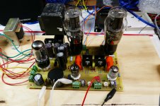
Using nothing more than a voltmeter to test the voltages, set the bias on the output tubes, and plate voltage on the drivers, the board came right up and plays nice. It currently has Chinese 2A3's in it which have been worse case in the filament regulator department.
There will be at least one more iteration of the layout to fix some minor parts fitment issues. I'll look into adding some probe points for the major voltages, but I'm hesitant to mess with success too much.
The number one request for the new board was to improve this area. People complained about the dual heat sink, often saying it's hard to find (Digikey still has them), the area is too crowded, and gets too hot.
I addressed these concerns by incorporating individual heat sinks that are quite common (yes 1 inch tall), spaced then further apart, and modified the circuit to reduce the dissipation. After playing for over an hour I can put my finger on the heat sink without burns. NOTE, DON'T do this, they still carry B+ voltage unless insulators are used. The board can be assembled with the heat sinks (and other parts, except tube sockets) on the bottom side to allow for close to the top plate mounting. My next build up will be done this way to verify placement before sending out for boards.
In order to accommodate the heat sink requests, and the requests to increase the spacing between the output tubes, the board got larger in both X and Y directions. The placement of all 5 tubes moved with respect to each other, so I doubt existing cabinetry will work.
I'm going to let it play for the rest of the day while I work on Tubelab's taxes. Maybe later I'll try some different tubes or take some measurements.
would it be possible to add test points to the board?
There will be at least one more iteration of the layout to fix some minor parts fitment issues. I'll look into adding some probe points for the major voltages, but I'm hesitant to mess with success too much.
another aspect that can be (maybe) improved - please refer to the the MOSFETs and heat-sinks
The number one request for the new board was to improve this area. People complained about the dual heat sink, often saying it's hard to find (Digikey still has them), the area is too crowded, and gets too hot.
I addressed these concerns by incorporating individual heat sinks that are quite common (yes 1 inch tall), spaced then further apart, and modified the circuit to reduce the dissipation. After playing for over an hour I can put my finger on the heat sink without burns. NOTE, DON'T do this, they still carry B+ voltage unless insulators are used. The board can be assembled with the heat sinks (and other parts, except tube sockets) on the bottom side to allow for close to the top plate mounting. My next build up will be done this way to verify placement before sending out for boards.
take a pic of the old and new board side by side.....if it'll fit in my current wood open top cabinet.
In order to accommodate the heat sink requests, and the requests to increase the spacing between the output tubes, the board got larger in both X and Y directions. The placement of all 5 tubes moved with respect to each other, so I doubt existing cabinetry will work.
I'm going to let it play for the rest of the day while I work on Tubelab's taxes. Maybe later I'll try some different tubes or take some measurements.
Attachments
It's a high heat area too. I once had a pair of caps which the cover wrap melted due to the heat from those heat sinks.In my experience, this place was a tight fit for the sinks and the height was a challenge

It's a high heat area too.
Well understood, and fixed.
The TSE was designed with 45's in mind. It was the early 2000's and good used tubes could still be found on Ebay, in flea markets, and at hamfests for $5 to $10 each! At that time many of my amps were hand wired, and constantly evolving. Most were actually Push Pull amps using 6L6GC's or KT88's.
The discovery of "PowerDrive" brought the mosfets and PC boards into the picture. I can find pictures and Eagle files of at least 4 different versions of what became the TSE. Often the board changed to fit whatever parts I could get surplus, and all boards were DIY like the one in these pictures. They all went to my technical friends, who often built them themselves.
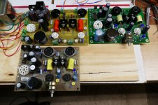
I couldn't make enough of them so myself and some friends decided to pool our money and get a batch of boards made for our 45 amps. I did the "final layout" for that design based on parts in the 2003 or 2004 Digikey catalog. We even got a bunch of different caps and took them into the plant to analyze them and picked the best....this is the reason for the huge cathode bypass caps. As with this board I made a prototype board to test the layout before spending money on a batch of boards. That proto board from 2004 is the one in the foreground of the 3 boards picture in post #63. It still works too!
There have been ZERO changes in the TSE board since then, but people (including myself) stuck bigger and bigger tubes into it, and line voltages keep going up, so it runs a lot hotter than in 2004. Time for a change.
In spite of the heat, the TSE has been a popular amp design once people got over the "sand in the signal path" thing. Therefore, I'm hesitant to make any major changes. The most popular request was "make it bigger." The amp looked funny when some fat 300B's were installed and they nearly touched each other. I stretched the board to the biggest size that would fit the mailing materials I use and used most of the room around the heat sinks, tube spacing, and the new heater supply (more caps).
The TSE was always marginal with 2A3 tubes since that eat 2.5 amps each. That was another design criteria for the new heater circuit. It has been playing for 3 hours now with 2A3's running 75 mA each at 125 volts AC line and nothing is excessively hot. I plan on tweaking some resistor values to even out the heat once 45's and 300B's are tested.
After about an hour I smelled something hot. Investigation revealed that the B+ choke I borrowed from an old HP audio oscillator really doesn't like 170 mA of current through it.
One more suggestion if it's not too late for consideration.
A fifth mounting hole in the center of the board somewhere might be a good idea. The shorter board flexes a bit when tubes are inserted and that will become more evident with the longer board.
A pair on the centerline at the edge would rock but I don't see a suitable location.
A fifth mounting hole in the center of the board somewhere might be a good idea. The shorter board flexes a bit when tubes are inserted and that will become more evident with the longer board.
A pair on the centerline at the edge would rock but I don't see a suitable location.
Thought I'd comment as an FYI in case you'd ever want to improve on the toner transfer process.
I've had good luck with HP brochure paper for toner transfer. It's a glossy and slightly heavier paper than regular copier paper. It's intended for laser printer use.
For the transfer, I use a cheapie laminator that I picked up new on eBay for something like $25. I had to chop off a part of the cover so the board would go through without interference. The heat and pressure of the laminator works really well for toner transfer. I run the board through a few times to get it nice and hot. Then sandwich between top/bottom layer printouts and run it through the laminator another few times. I'm able to get 0.25 mm registration on a good day.
Makes perfect sense to me. Also, if it ain't broken, don't fix it. With large parts you can live with quite a bit of registration error - especially for a prototype.
Tom
This is a DIY proto board that was made using an iron on toner transfer method. My printer can't make two identical prints, and the paper itself goes through thermal shock when the hot iron hits it. These protos will have registration issues between the two sides and well as several other less than desirable traits like lack of plated through holes.
I've had good luck with HP brochure paper for toner transfer. It's a glossy and slightly heavier paper than regular copier paper. It's intended for laser printer use.
For the transfer, I use a cheapie laminator that I picked up new on eBay for something like $25. I had to chop off a part of the cover so the board would go through without interference. The heat and pressure of the laminator works really well for toner transfer. I run the board through a few times to get it nice and hot. Then sandwich between top/bottom layer printouts and run it through the laminator another few times. I'm able to get 0.25 mm registration on a good day.
They will never leave my lab, so I live with the drawbacks in order to eliminate the time and $$$$ for one or two off boards.
Makes perfect sense to me. Also, if it ain't broken, don't fix it. With large parts you can live with quite a bit of registration error - especially for a prototype.
Tom
How about 6C45pi?.....So no viable alternatives to the 5842?
E180F is also suggested in earlier posts.
Last edited:
Hi George,
Here's another suggestion for the revised board.
Would it be possible to change the orientation of the power sockets so that the tube labels will face forward? I believe this would mean that pins two and three are in the rear and pins one and four are in front.
I like the suggestion of adding a center mounting point to add stability to the board.
take care, Jacques
So no viable alternatives to the 5842?
I went through every tube in my collection back when I designed the TSE, and found nothing that works as good as the 5842 or the WE417A.
About this time last year I rigged up a TSE board to test some tubes. I had a bunch of WE471A's that I was selling, and they had to be tested. I used a TSE board without any output tubes to test and match about 15 417A's and 50 some 5842's. Each tube was driven with an audio signal generator to approximately 100 volts P-P output, adjusted for minimum distortion, and the DC, gain and distortion readings recorded.
As expected the WE tubes had lower gain (their Mu is 44) compared to the Raytheon 5842's (Mu = 50). The WE's were more consistent in the DC voltage readings and produced the lowest distortion. How many tubes can make 100 volts P-P at less than 1/2 percent THD? Most of the WE 417's did.
The Raytheon 5842's were less consistent in DC bias which is why there is an adjustment pot in the cathode circuit. All but a couple of these tubes were below 1% THD at 100 volts P-P. ALL tubes were used pulls from old military and telephone company spare equipment.
I have recently gone through several more possible choices for driver tubes, but nothing I have tested is consistently this good. The 5842 was fairly common and about $5 each when I designed the TSE. Any new choice that isn't current production must be available in fairly large quantities, and that is another design criteria that must be considered. Will there be a TSE-III if and when I find one? I don't know, but I do know that the TSE will be long forgotten if I hold up the TSE-II until I find it. For now the 5842 must remain.
How about 6C45pi?
I don't have any 6C45's, and I would need several to find out if they were suitable. It seems that it's one of those love it, or hate it kind of things from it's reputation. At this stage of the game I'm hesitant to mess with a successful design until I have the time and funds to do some extensive testing.
E180F is also suggested.....How about the in production ECC99
The ECC99 does fall short in gain. Even the WE417A is marginal if driven from a low output source.
Like it or not, the TSE has garnered an "audiophile" type reputation in stark contrast to its early days when many people cried foul because of the silicon in the signal path. More than once it was suggested that I change my company name to Transistorlab.
There are still plenty of people who refuse to try it, but that is now the minority. There would likely be resistance to using a triode wired pentode as the driver even though there ARE some that work quite well. Consistency is still an issue. Another possible choice for a driver is the venerable 12AX7. SOME of them can produce astoundingly low distortion numbers, but some really suck. How does an end user without test equipment know which is which? .....these possibilities will be explored in depth in the modular "building block" versions of the TSE and other designs.
change the orientation of the power sockets so that the tube labels will face forward?
Every tube is different. You can see the labels on the front of my 2A3's in the board the way it is now. It would take a complete redesign of the board to move those two FAT traces capable of carrying 2.5 amps. That's not possible now that I have a working board that just needs minor tweaks.
I like the suggestion of adding a center mounting point
That one was on my list as the SSE already has 5 holes, and I missed it. I am in the process of fitting it in now, which will mean one or two more test board spins before sending the board out.
label the parts on both sides of the board to facilitate dual side assembly?
That is possible. I need to see If my board house will do it, and how much it will add to the price.
Would a company like JJ accept the challenge of making a new tube with similar specs? Other manufacturers?
Just curious what triggers a new model for these companies... Can we convince them there is a market for them?
Let’s say JJ or Electro-Harmonix we’re to do a 417A reissue, the central question would be whether they have the ability to repeatably achieve the low distortion figures of the originals.
Those originals were made by Western Electric to service their own needs. Namely a low distortion tube that would allow amplification of a multiplexed signal with many hundreds of calls without creating crosstalk. It was a demanding application and poor performance was obvious. If you’re old enough, you will have experienced long distance calls with someone else joining your conversation.
While I’m thankful that these companies are in business and generally satisfied with their products , I’m a bit sceptical that they could produce an equivalent 417A and make a profit doing so.
produce an equivalent 417A and make a profit doing so.
Look what a new production JJ 6386 goes for.
I have no idea how well these work, and don't know anyone who has tried them. I have several good used ones and one NOS GE still in its box. They will be used as reference standards for my tube VCA, to be designed with cheap tubes.......some day, then sold.
The original 6386 was an RF amp tube used in a military radio in the 1950's. Few were made, but it found duty in the Gates Sta-Level, and Fairchild audio compressors used in radio stations.
These compressors have become worshiped by today's trendy recording studios to the extent that a working original goes for north of $20K. And you thought that audiophools spent big money on their toys.....
JJ 6386 LGP Preamp Vacuum Tube
| TubeDepot.com
My WAG is that if you already have an actual manufacturing facility up and running, the marginal cost of putting additional types back into production is probably not that great.
Tube Depot runs 417A's on sale pretty often, so there may not be much demand for the type.
I have some that are dual marked as 417A/5842 - I wonder if they are the "high" mu or "low" mu variant. They are trade dressed as early 1960's RCA, but I suspect they are Amperex made because of the gold pins. I don't think RCA ever made either type.
I seem to recall a QEX article in the late 80's or early 90's comparing 417A to the low noise RF FET's that ordinary people could purchase at that time. 417A was still as quiet or quieter up to 144 MHz. Again, IIRC.
Win W5JAG
I have some that are dual marked as 417A/5842
I had a few that were marked "Ericsson" like the cell phone company from the 90's. Don't know if they made them or not, but they were different from either the WE or the Raytheons. I don't have them any more. I do still have one Tung Sol and it was stuck in the TSE-II in the pictures. It's different internally form the Raytheon or WE, but works like a Raytheon. I suspect a lot of different flavors existed when they actually went into phone systems.
I bought a pair of WE 417A's a few years back, maybe more.
Almost sh*t when I saw how much the normal price is at Tube Depot
417A Western Electric
| TubeDepot.com
Almost sh*t when I saw how much the normal price is at Tube Depot
417A Western Electric
| TubeDepot.com
- Home
- More Vendors...
- Tubelab
- After a 14 year run, the TSE must DIE!