Toroidy is also high on my list! I’ve heard a lot of good things about them, but didn’t realise the price difference is this big. I’ll definitely send them a message. I was thinking of getting 2.5k primary, but still not decided on secondary, probably 8ohm. In the future I would like to try the tse-II with some lower impedance headphones too, but not sure about noise floor.After several PM's it was discovered that his board is an original TSE. The sharp regulator has been extinct for several years, and TSE builders or hoarders used up most of the remaining stock. The 10M45S chips are on the forever backlog list now too along with the MIC29502. Amazon shows stock in the 29502, I have never tried them to see if they are real.
Let's see, You are looking to buy OPT's from the USA, and I just got some OPT's from Poland. The EP transformers are good, but so are Toroidys which are far less money than the EP's even with shipping. I got mine from TME.
George, All,
I'm getting ready to build one of the TSE-IIs. I got a board from you recently. It will be a 300B.
I believe the DN series from Microchip/Supertex works relatively similarly to the 10M4CS and could be dropped in... would have to be tested.
One question is whether the TSE page on George's website is still okay for figuring out things like operating points, etc., because the B+ voltage is not stated on the schematic, presumably because the user is expected to figure it out . For 300B, about 350-360V at 75 mA is recommended by George. Is that applicable to TSE-II? I think it is but want to confirm.
With regard to the LDO regulator, how about the 29503 part from Microchip?
https://www.mouser.com/datasheet/2/...75x_High_Current_Low_Dropout_Regu-1889172.pdf
Thanks!
I'm getting ready to build one of the TSE-IIs. I got a board from you recently. It will be a 300B.
I believe the DN series from Microchip/Supertex works relatively similarly to the 10M4CS and could be dropped in... would have to be tested.
One question is whether the TSE page on George's website is still okay for figuring out things like operating points, etc., because the B+ voltage is not stated on the schematic, presumably because the user is expected to figure it out
. For 300B, about 350-360V at 75 mA is recommended by George. Is that applicable to TSE-II? I think it is but want to confirm.With regard to the LDO regulator, how about the 29503 part from Microchip?
https://www.mouser.com/datasheet/2/...75x_High_Current_Low_Dropout_Regu-1889172.pdf
Thanks!
Last edited:
Yes the circuit is the same as the original with the exception of a few minor tweaks, like the filament voltage regulator.......a new part had to be sourced due to the old part becoming obsolete.......the output tubes are spaced further apart for heat dissipation, and a few other things. As far as the operating point goes, 350-360V and 75ma is typical. You could push the voltage or current a little higher but it all comes down to power dissipation and tube life. 300B's are somewhat $$ so the above operating point is a nice compromise. I think those volts/ma provide about 8W or so output.One question is whether the TSE page on George's website is still okay for figuring out things like operating points, etc., because the B+ voltage is not stated on the schematic, presumably because the user is expected to figure it out
I'm running my original TSE at 360/75ma and it's my favorite amp.
Last edited:
The audio path for the TSE and TSE-II are identical, so all setup instructions from the TSE apply to the TSE-II. The original TSE worked great even when pushed far beyond its original intention as a 45 based amp, so why mess with success. Running a small board originally intended for small tubes with some much bigger tubes did make for a rather hot running amp, but they worked great. When the regulator chip went extinct a redesign was needed, so in the early pages of this thread I asked for inputs and accommodated most of them. BIGGER, with more space (811A's touch each other in the old board), and some other heat mitigation solutions were the most popular requests.
The IXYS IXCP10M45 has become rather hard to find today. I have used the DN2540 for voltages below 400 volts in the TSE-II, and used the IXYS IXTP01N100D successfully in similar applications, but I have not actually tried them in the TSE-II. In either case the source resistor that determines the current will need to be determined experimentally.
The 29503 part should work for the filament regulator except that pin 1 must be bent up, cut off, or otherwise not connected to the board. Pin one is the enable INPUT on the 29502 part, so it is connected to the supply input to strap the part into always on mode. Pin one is an open collector OUTPUT on the 29503 part and the emitter of that internal transistor is grounded. The part will attempt to pull the raw filament supply to ground, and it will lose that fight. Again, I have not actually tried that part because I don't have any. I have some TI parts that might work, but they are not specified to work above 6 volts on the input. A TSE-II board configured for 5 volt tubes with no tubes installed can put about 7.5 volts on that chip. I will test the TI parts to find where they really break, but it will be a few weeks as I'm busy gathering up all my excess "stuff" for a trip to the Dayton Hamfest to sell a lot of things that I will never use.
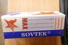
There are three intended use cases for the TSE-II board, the 45 tube, the 2A3 tube, and the 300B tube. There have been several amps built with the TSE and TSE-II boards that I never intended or expected. I have seen amps running small DHT's for driving headphones on 200 volts or less, and some transmitting tube versions running over 500 volts. There are also a lot of different things called 300B being sold today. A genuine WE 300B, or a reasonable clone is specified for 360 volts and 75 mA. The original Sovtek 300B proudly claims operation to 450 volts right on the box. Don't go there though. A properly made tube may handle 450 volts for a while, but any Sovtek that I ever tried would go into runaway at anything over 400 volts. One of the recommended operating conditions stated on the box is 450 volts at 80 mA. There are some very pricey UBER 300B's out there that will run at these extremes and beyond. The TSE-II will accomodate them. I also stress tested my TSE-II with budget Chinese 2A3's in it on 380 volts at 75 mA for nearly a year with no issues. It only got pushed off the bench so I could listen to an UNSET for a year.
This is why there is no hard and fast rules, or even recommended B+ voltage for the TSE or TSE-II. Most builders run 300B's in the 360 to 400 volt range and at currents from 60 mA to 75 mA with a 3000 ohm OPT. My Yamaha NS-10M STUDIO monitors seem happiest when driven by a tube running a higher than normal load impedance with a B+ voltage near the upper end of the tube's spec, so I ran Chinese 300B's at nearly 400 volts at 75 mA into a 5K ohm OPT.
The IXYS IXCP10M45 has become rather hard to find today. I have used the DN2540 for voltages below 400 volts in the TSE-II, and used the IXYS IXTP01N100D successfully in similar applications, but I have not actually tried them in the TSE-II. In either case the source resistor that determines the current will need to be determined experimentally.
The 29503 part should work for the filament regulator except that pin 1 must be bent up, cut off, or otherwise not connected to the board. Pin one is the enable INPUT on the 29502 part, so it is connected to the supply input to strap the part into always on mode. Pin one is an open collector OUTPUT on the 29503 part and the emitter of that internal transistor is grounded. The part will attempt to pull the raw filament supply to ground, and it will lose that fight. Again, I have not actually tried that part because I don't have any. I have some TI parts that might work, but they are not specified to work above 6 volts on the input. A TSE-II board configured for 5 volt tubes with no tubes installed can put about 7.5 volts on that chip. I will test the TI parts to find where they really break, but it will be a few weeks as I'm busy gathering up all my excess "stuff" for a trip to the Dayton Hamfest to sell a lot of things that I will never use.
There are three intended use cases for the TSE-II board, the 45 tube, the 2A3 tube, and the 300B tube. There have been several amps built with the TSE and TSE-II boards that I never intended or expected. I have seen amps running small DHT's for driving headphones on 200 volts or less, and some transmitting tube versions running over 500 volts. There are also a lot of different things called 300B being sold today. A genuine WE 300B, or a reasonable clone is specified for 360 volts and 75 mA. The original Sovtek 300B proudly claims operation to 450 volts right on the box. Don't go there though. A properly made tube may handle 450 volts for a while, but any Sovtek that I ever tried would go into runaway at anything over 400 volts. One of the recommended operating conditions stated on the box is 450 volts at 80 mA. There are some very pricey UBER 300B's out there that will run at these extremes and beyond. The TSE-II will accomodate them. I also stress tested my TSE-II with budget Chinese 2A3's in it on 380 volts at 75 mA for nearly a year with no issues. It only got pushed off the bench so I could listen to an UNSET for a year.
This is why there is no hard and fast rules, or even recommended B+ voltage for the TSE or TSE-II. Most builders run 300B's in the 360 to 400 volt range and at currents from 60 mA to 75 mA with a 3000 ohm OPT. My Yamaha NS-10M STUDIO monitors seem happiest when driven by a tube running a higher than normal load impedance with a B+ voltage near the upper end of the tube's spec, so I ran Chinese 300B's at nearly 400 volts at 75 mA into a 5K ohm OPT.
Attachments
I built an F4 and yes you can certainly do that and you will get very good results.The First Watt F4 has no voltage gain and one of the ways you can use it is to hook up a low powered valve amp to its inputs to provide the gain. Any reason why the TSE 2 would not be a good choice for use in this way?
I drove my F4 with a number of tube amps over the years. Now, I drive it with my tube dac and that’s my favorite overall combo of anything I’ve built or owned.
Cheers,
Greg
https://www.diyaudio.com/community/threads/diy-tda1541a-pcb-d3.328060/Could you link to your tube DAC?
That’s just the dac board. I use an Abbas Audio tube OPS board designed for the TDA1541. Read the thread and PM me, that way we can keep the discussion out of this thread.
Yes, but you might need to change the source resistor value.I am sure this has been asked before but here goes. Can the IXCP10M90S be substituted for the IXCP10M45S?
I picked up some 10M45S regulators from Ebay just recently. They look like the real thing and are working fine in my UNSET. What I did was setup a test jig with a 330 ohm resistor and measured the current with my DMM. I found they varied 3mA between the highest and lowest values measured with a target of 10mA. For the UNSET I selected a close pair then just dialed them in with the resistors. The rest I will use with an adjustable pot. I don't know what the standard variance is for these but +- 15% seems high. Perhaps these fell outside that range when testing so ended up on eBay?
I have just bought a few GZ37 and would like to use one with the TSE-2. Has anyone tried this yet and did you change the first
I modified the TSE-2 for the GZ37 and also a pair of EML 300B XLS tubes.
I changed the 47uF cap for a 10uF 900V cap and the 150uF cap for a 200uF 1000V cap. I removed the motor run cap.
I also changed the 1uF 450V cap for a 630V version.
With the 300-0-300V tap I was getting a B+ of around 380V before modifying the caps with a GZ34 and EH 300B.
The GZ37 gives about 10V less B+ than the GZ34.
Now I am getting only 395V B+ with the 350-0-350V tap. I was hoping to reach about 450V.
I will try a 383-0-383V transformer, but I don't think it will get me to 450V.
Any suggesties what I can do to reach 450V?
Not sure if I can use much more than the 10uF first cap with the GZ37, but I have some 22uF also.
How much current are those big XLS type consuming?
You are going from 370 Vdc to 395 Vdc (+25V) with an AC supply increase of 50V (70Vpeak)?
Smells like increased current to me (the winding resistance increased a bit too going from 300V to 350V on the same PT).
You are moving to a larger rectifier because you need the extra current?
Finding no GZ37 graphs, I looked at the GZ34 graphs: to reach 450Vdc at 150mA or more, you need 400-0-400, depending on transformer resistance and capacitor value.
The GZ37 is generally used with a 4uF cap. 10 should be ok, but you don't want to burn out these rare tubes too fast.
Because I only reached 395V, I have them at 60mA. The goal was 450V and 80mA.
The transformer can deliver 250mA, so it should be fine.
I don't need extra current, I just liked the look of the GZ37 and was able to buy 4 of them cheap. I also was running out of Mullard or Philips GZ34. Probably
with the GZ34, I would have reached 405V, maybe 410V. I could try this.
Unfortunately I don't have a 400-0-400V transformer and my 383-0-383V transformer is 180mA. With the 300B XLS at 80mA each, there is not much reserve left. It is a Tektronix transformer, so it probably will deliver a bit more than 180mA. Hope this transformer will give better results. I have 9 of these transformers, so I can afford to blow one up, but hope not.
What’s the part # of the Tektronix power transformer you use?
Do you have a schematic of the power supply using the Tek transformer?
Thanks,
Tech
Do you have a schematic of the power supply using the Tek transformer?
Thanks,
Tech
Because I only reached 395V, I have them at 60mA. The goal was 450V and 80mA.
The transformer can deliver 250mA, so it should be fine.
I don't need extra current, I just liked the look of the GZ37 and was able to buy 4 of them cheap. I also was running out of Mullard or Philips GZ34. Probably
with the GZ34, I would have reached 405V, maybe 410V. I could try this.
Unfortunately I don't have a 400-0-400V transformer and my 383-0-383V transformer is 180mA. With the 300B XLS at 80mA each, there is not much reserve left. It is a Tektronix transformer, so it probably will deliver a bit more than 180mA. Hope this transformer will give better results. I have 9 of these transformers, so I can afford to blow one up, but hope not. View attachment 1058261
- Home
- More Vendors...
- Tubelab
- After a 14 year run, the TSE must DIE!