TSE Wandering Bias; Midnight Report
I had the amp stable, and biased at 75 mA, then shut it off for a cool-down ( plus dinner).
After a long cool-down, bias at restart was about 35mA. Extrapolating from the rate of increase, looked like it would take a hour or more to reach the 75 mA set-point, so I raised the bias to 60 mA and monitored/adjusted. Obviously raising the bias increased the heat in the chassis, which got it to steady-state faster, but this is no way to live.
Obviously, I need to reduce whatever thermal effects are happening.
Tomorrow, will add Heatsink to the unused holes for the second channel and “strap” them to the existing 10M45 and MOSFET Heatsinks with brass shim stock.
HOWEVER, I have nagging worry that over-heated “sand” is only part of the problem, and that I’ve got hot resistors, e.g. in the bias voltage divider, which are throwing-off the bias.
Once it warms-up, it’s very stable, and sounds fantastic biased around 75mA, clear, clean, superb detail, and Real Bass from a DHT....Dave Brubeck’s Take Five album on there now; “simply LYRICAL” is what the capital-A Audiophiles would say...
Any suggestions where the trouble might be OTHER than “hot sand”?
Otherwise, I’ll just keep sneaking-up on it...
Thank you very much for your comments!..
I already have built a KT88 se amp and a small ECL82 amp, and my next target for experimenting is a triode amp, operating at as-non-lethal-volages-as-possible... i d looooove a BRIGHT 805/845/811/gm70 amp, but it would be rather dificult for me, it would require dificult and expensive parts etc.. I have very good soldering experience, i am good at following a specific schematic-built, but unfortuantely my knowledge is limited to house electrical instalation stuff, and not electronics.. i can do some basic measurments, i do understand stuff as good and tight contacts, good isolation etc.. but i cant modify a circuit, i cant do more complex measurments...
The KT80 SE built and the ECL82 built, worked fine from the begining, the sound nice, so i left them as is..
I have a VERY good 4xkt120 pp - schematic, and a friend to guide me, but still i am afraid to start it as it is rather complex for my teeth...
SO, i would love to experiment with a triode design, on PCB for ease of built and safety, as bright/simple/safe as possible.. i have quite many parts, good caps, irons etc.. i might even have output and psu traffos.. sound quality is not my priority.. i cant afford expensive and exotic materials..
My initial search was in ebay , and i found two pcb's, one from Jim's audio and one from hifidiy.net , but i want to be sure at least that the design is correct.. as i was googling around i stumbled on tubelab site and it looked very corect and interesting...")
I am building a nice, retro old-school looking and sounding system, to pair my DUAL pickup and a nice small pair of 3"Audio Nirvana's that i have almost ready.. it will be a very sweet sounding system for old lp's , casettes and fm radio broadcasts..
I already have built a KT88 se amp and a small ECL82 amp, and my next target for experimenting is a triode amp, operating at as-non-lethal-volages-as-possible... i d looooove a BRIGHT 805/845/811/gm70 amp, but it would be rather dificult for me, it would require dificult and expensive parts etc.. I have very good soldering experience, i am good at following a specific schematic-built, but unfortuantely my knowledge is limited to house electrical instalation stuff, and not electronics.. i can do some basic measurments, i do understand stuff as good and tight contacts, good isolation etc.. but i cant modify a circuit, i cant do more complex measurments...
The KT80 SE built and the ECL82 built, worked fine from the begining, the sound nice, so i left them as is..
I have a VERY good 4xkt120 pp - schematic, and a friend to guide me, but still i am afraid to start it as it is rather complex for my teeth...
SO, i would love to experiment with a triode design, on PCB for ease of built and safety, as bright/simple/safe as possible.. i have quite many parts, good caps, irons etc.. i might even have output and psu traffos.. sound quality is not my priority.. i cant afford expensive and exotic materials..
My initial search was in ebay , and i found two pcb's, one from Jim's audio and one from hifidiy.net , but i want to be sure at least that the design is correct.. as i was googling around i stumbled on tubelab site and it looked very corect and interesting...
I am building a nice, retro old-school looking and sounding system, to pair my DUAL pickup and a nice small pair of 3"Audio Nirvana's that i have almost ready.. it will be a very sweet sounding system for old lp's , casettes and fm radio broadcasts..
Last edited:
Re: Taller Sinks
Yup, I ordered a bag of ‘em from Mouser.
In the meantime, I tacked-in the #2 MOSFET heat sink, and strapped together the two sinks with a SIZEABLE strip of brass shim stock.
STILL getting a significant rise in bias current between cold start-up and steady-state stability, but I’m running thru a cold-hot-cold cycle right now to see what the numbers actually are.
The “temperature coefficient of bias current” is much better with larger sinks, but I suspect it’s still gonna be pretty, pretty, pretty large, which is why I’m looking elsewhere....
Re: Bias Resistors
ALL resistors are off the board, even the tiny 1/4W ones; I just do this as standard practice.
What I need is a list of potential causes for a large upward drift in bias current from cold start-up to “warm” (i.e. HOT) I’ll probably get there eventually on my own, but it would be faster if I had a list of usual suspects, rather than waiting for my pea-brain to think of something in the shower at 1 AM.
There are 4 ways a triode can drift upward over time / temp.
The first is a bad / gassy tube.
The second is that the plate voltage creeps upward with time or increased temp.
The third is that the bias voltage on the grid goes less negative with time or increased temp.
The fourth is an increase in filament voltage with time or increased temp.
You may have a combination of these things going on. You need to monitor the voltages over a warm-up cycle to see what's moving.
Your box design has no ventilation, so most of the heat generated under the deck is trapped there. Installing larger heat sinks may be of little help if the temperature under the deck goes into the 70C+ range. I see that you have some wood pieces to allow for air to enter underneath, but it has no way out except for a few small holes. That thick wood is a pretty good heat insulator too.
I usually create a rabbet around the outer edge of the top plate with my table saw so the hot air is vented by the gap around the outer edge of the deck. You might try raising the deck a bit with some washers to see if that helps.
I noticed that you were using parts values from the text associated with the original TSE. You have 39K for R25. That value was needed to reduce dissipation in the mosfets for high B+ voltages. Now that the mosfets run from a fixed 150 volts on their drains, that's no longer necessary, and the parts list reflects 20K for all builds. However, putting a 20K in there now will only raise the current through the mosfets, and R36, thus putting more heat under the deck.
Another thing that some users do is to get a heat sinkable resistor for R36 and mount it to the top plate itself. Wire length for R36 is not an issue.
R36 was the culprit
TubeLab said:
"Another thing that some users do is to get a heat sinkable resistor for R36 and mount it to the top plate itself. Wire length for R36 is not an issue."
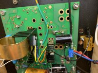
It became obvious, even to this codger, that the heat generated by R36 was getting trapped and sucked-up by the Q2 heat sink and cooking the MOSFET.
Instead of the ridiculously easy and obvious solution of MOVING R36 off the board (and maybe "up-watting" it) as George mentions, I moved Q2 over a slot (as this is a monoblock, so that slot is unused), used my last large AAVID heatsink, and ran 2" jumpers.
I left the Q2 heatsink in place as a "heat shield", plus lazy.
Bias rise from dead cold to steady state appears to be down to single-digit milliamps. Jumpers appear to be short enough; can't hear any audible artifacts.
Just for "belts and suspenders" I'll move R36 off the board, maybe upgrade to a big heatsinked power resistor and attach it under the deck.
Note that I've enlarged and increased the holes in the top plate since the first pictures. The wood sides are of course good insulators, but I need to work-around to preserve the WAF...
TubeLab said:
"Another thing that some users do is to get a heat sinkable resistor for R36 and mount it to the top plate itself. Wire length for R36 is not an issue."
It became obvious, even to this codger, that the heat generated by R36 was getting trapped and sucked-up by the Q2 heat sink and cooking the MOSFET.
Instead of the ridiculously easy and obvious solution of MOVING R36 off the board (and maybe "up-watting" it) as George mentions, I moved Q2 over a slot (as this is a monoblock, so that slot is unused), used my last large AAVID heatsink, and ran 2" jumpers.
I left the Q2 heatsink in place as a "heat shield", plus lazy.
Bias rise from dead cold to steady state appears to be down to single-digit milliamps. Jumpers appear to be short enough; can't hear any audible artifacts.
Just for "belts and suspenders" I'll move R36 off the board, maybe upgrade to a big heatsinked power resistor and attach it under the deck.
Note that I've enlarged and increased the holes in the top plate since the first pictures. The wood sides are of course good insulators, but I need to work-around to preserve the WAF...
Life in the Big City..
Went down the street to ACE Electronics and grabbed a couple of nice 10K, 25W resistors, because why not.
Running another cold-hot-cold cycle, but looks like this may do the trick.
If not, more ventilation around the perimeter...
Went down the street to ACE Electronics and grabbed a couple of nice 10K, 25W resistors, because why not.
Running another cold-hot-cold cycle, but looks like this may do the trick.
If not, more ventilation around the perimeter...
Attachments
TSE-II 300B Monoblock Deck Temps
Got out the trusty (i.e. cheap) IR pyrometer, slapped-in a new battery, and measured temps of the steel deck, approximately above various components:
R36 134 deg F (now off-board)
Q2 106 (in the Q2 location)
10M45 105
D1 107
IC3 109
R6 113
Rest of deck runs 95-100 deg F
PST 94 deg F
choke 85
OPT 78
Ambient is ~74 per pyrometer.
The wood chassis runs about 78 deg F
After 1-1/2 hours holding steady at 62mA bias at 375 Vp
Loose 4-Pin Socket
I wanted to build these TSE-IIs with parts on hard as much as possible.
Unfortunately, that meant using ancient 4-pin ceramic sockets which are at least 20 years old and VERY used.
While watching all the voltages, suddenly got a spike over 400 V.
Sheit. Merde. Crash the Rods. Went to wiggle the 300B (itself a decade old) and it was flopping around in the socket like a carp in the bottom of a canoe. (Don't ask).
With a little judicious "prising" (as my British friends would say) with a tiny awl, and I had put a small arc in the outer contacts.
Nice and snug. No floppage.
Start-up measurements: 380Vp, -100 Vgrid (on top of R26), 0.600V across R29 Plate sensing resistor =~60mA.
Pretty stable, although a very small amount of "thermal creep" as it gets hot.
Last edited:
Ordering TSE-II
(1) Pricing is on Post #1 of this thread
(2) "How to Order" via PayPal is at Ordering | Tubelab
(3) NOTE that the USA-built TSE-II boards are out of stock, and TubeLab George is still TORTURING the next batch (from China) and has not, AFAIK, released them for sale.
I'm ready for a couple more, so waiting with bated breath.
The Chinese boards are working fine, and available. I started sending them out on Tuesday. I noted this in the first post.
So its 40+15$ for shipping to Greece right?..
sorry for my ignorance, i ve never ordered something from within diyaudio.. i am newbie.. 🙈
one last question , cause i cant find the answer.. TSE-II is an integrated amp or a power amp?. whats the input level ? (sorry for my so so english , i hope you understand what i mean)
Depends on your definition of “integrated”.
There is no preamp for low-level signals like phono, and there are no tone circuits.
It takes line-Level inputs (e.g. CD player, most digital sources).
You can build it with or without a volume control.
I am building monoblocks 300B TSE-II POWER amps (i.e. w/o volume controls) but next will be building a stereo 45/46 amp with volume controls.
So i guess that with a pot, it can be directly fed by my soundcard line out.. super.. i dont need phono or tone controls... I guess that it suits me greatly!..
This Weekend i ll check the BOM and my parts stock, and i ll make my decision.. i ll also see my irons , to see if i can save some euros from there too , as i have some stuf around.. Thanks!
This Weekend i ll check the BOM and my parts stock, and i ll make my decision.. i ll also see my irons , to see if i can save some euros from there too , as i have some stuf around.. Thanks!
Volume Controls
You can use the volume control on your computer if you like.
My office set-up had THESE volume controls:
(1) Windows 10 laptop
(2) Spotify "app"
(3) External DAC (Topping DX-3)
(4) "PhonoDude" pre-amp (with a passive section to select source)
(5) SET amp
The bold ones are digital; the other two are analog potentiometers.
Spotify can be controlled with a smartphone.
The DAC has an IR remote control.
I eliminated the volume control on the last SET build, since FOUR volume controls with TWO remote controls is probably enough.
New Vs. Old TSE-II boards
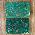
Two new-style TSE-II boards arrived lickety-split from George.
Here’s a shot of new (dark) vs old (light).
Tilted to avoid reflected ceiling lights in the shop.
The new board actually LOOKS better, as the component labels are easier to read against the dark green. We’ll see how they hold-up to Ham Fisted soldering/unsoldering....
Old board weight: 93 grams
New board weight: 98 grams
That’s probably a good sign.
Attachments
- Home
- More Vendors...
- Tubelab
- After a 14 year run, the TSE must DIE!