Not sure about commercial availability but quite easy to diy. An android combined with an ACS current module and an SSR would be one of the simple route for diyers, add another SSR and a power resistor for inrush limiter.Is there an approved commercial component that works like this. ..
Not sure about commercial availability but quite easy to diy. An android combined with an ACS current module and an SSR would be one of the simple route for diyers, add another SSR and a power resistor for inrush limiter.
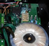
Inrush current limiter working with CMOS logic (timing) and standard approved fuses, shown in the photo. Absolutely reliable, numbers of them working in many amps.
BTW, I will check Ed's statements by measurements on the real amplifier.
Attachments
Demian,
84 volts would be a 6 dB power compression as the equivalent load resistance doesn't change.
I think we both understand the loss of power occurs from peak clipping of the AC power line sine waveform. As many folks may have the supposedly maximum distortion already of 5% that will affect their power output capability already and change the effects.
As I think you are aware properly sizing a fuse to avoid startup failures and insure safe operation is a bit tricky. A useful test is to monitor the voltage across the fuse. As we were talking about the case of a 100 watt amplifier potentially a class AB type the issue at differ from larger amplifiers as the fuse value will go up.
Another fun bit is the fuse type 5 x 30 mm fuses have lower loss than 3AG types for the same ratings!
As to a 3 dB power loss for a 100 watt amplifier that would only be a 21 volt drop at a RMS current of above 1 amp (the exact value depending on efficiency.) it should not surprise you some of the cheap time delay fuses can have hot values well above 2 ohms.
Pavel,
Keep in mind you have higher AC mains voltage and as you probably do not have 3AG fuses I would expect much lower losses, particulary with anything fusing a decent size amplifier. But if curious try looking at the voltage across the fuse. Don't forget to check for AC mains peak clipping as that increases the capacitor peak voltage charging time. I think you will find it interesting.
Looking at your posted image I see three fuses, unsure of the physical size, that implies rail fusing. As mentioned if you have an output transistor fail by shorting, the amplifier will try to keep the output voltage stable. In the case where that should be zero volts or close to it, the opposing good output side will conduct maximum current. Not surprisingly this will blow a fuse on the power rails. Once one fails it will lower the current and protect the other fuse.
Now if the good side fuse fails one rail will now be connected directly to the load. Even if the bad side fuse blows in many amplifier circuitry topologies the lack of current from the failed rail will force the good side to deliver current to the output! In older professional amplifiers a DC offset relay was triggered to try and prevent damage to the load. Warranty claims including damage to loudspeakers that could cost more than the amplifier served to correct most failure mode protection errors.
Last edited:
Of course Pavel. I even use worse performing NTC on mine. I was only pointing that better toys (than jewelry grade fuses) have been available for decades. Perhaps interesting to those who prefer to squeeze to the last drop.... Absolutely reliable, numbers of them working in many amps...
So you mean one of these ?.Well in the spirit of JC’s subjective side i’m gonna tell you about my latest endeavors with my nemesis of the last year or so.....the halo integrated.
In the past couple days of testing with these I’ve found some interesting things....


Dan.
Hey Dan,
Yes, except mine is the first version.....the exact same, but without the new resistor volume control, and only one set of dig inputs.
Yes, except mine is the first version.....the exact same, but without the new resistor volume control, and only one set of dig inputs.
Last edited:
Are all these opamps outside of the signal chain? If not, I would be very much interested in learning John's choice.
You can moderate the forum for real by either obtaining an official moderator position here or start your own forum.Good, now you know assumption can be twisted, including your own. Seems that you are not in command of sufficient intelligence to be a mole, but there still is a possibility of acting. If you are not a mole stop creating situations resulting in discomfort of other members, and I do not include those your posts are addressed to. If you are or becoming one, it is just a matter of time for the mods to kick you out.
Are all these opamps outside of the signal chain? If not, I would be very much interested in learning John's choice.
Yah anything would be helpful......this piece really has potential to be better.
He mentioned all the connectors being an issue.......are those something that could be soldered?
Would like to figure out where any other fuses are?
Edit.....here’s the internals of the one I have (V 1.0)
https://www.parasound.com/product-images/hint_black_inside.jpg
Thanks,
Bob
Last edited:
Ok, looks like newer version has electronic volume control with numerical readout instead of your motorised pot.Hey Dan,
Yes, except mine is the first version.....the exact same, but without the new resistor volume control, and only one set of dig inputs.
The reviews are good to it and the crossover/subout function is worth its' weight in gold.
Any comments on what power amp stages are in it JC ?.
Dan.
Next an amplifier drawing a mere 120 watts from a 120 volt AC power line does not draw 1 amp peak current (what the fuse responds to!) It easily will see a minimum of 10 times that. So the simple fuse resistance will make a 12% difference in maximum power output. A level that would be considered perceptible by most.
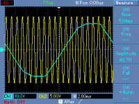
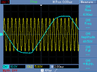
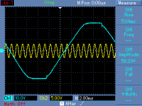
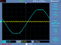
Ed, I was curious when reading your post 😉. So I made some measurements, to get a bit rigorous. I used an amplifier rated at some 2 x 120W/4ohm. The block diagram is attached. It is a bridged amplifier, so it has quite low supply voltage. The amplifier has one transformer with 2 separated secondaries for the two channels. I loaded left channel with 4 ohm and changed output power of this channel from 0.1W to 114W. The second channel, the right channel, was left unloaded. I measured transformer secondary voltage of the unloaded channel, which should reflect the primary voltage changes pretty well. Here are the results I got, shown as secondary power in W/Vp-p (peak to peak) secondary voltage.
0.1W/50.29Vpp, 3.6W/50.29Vpp, 26W/49.9Vpp, 57W/49.5Vpp, 114W/48.71Vpp. One can see that at 114W Vpp voltage is still 96.86% of the Vpp at negligible output power. There are 4A and 2.5A fuses used as shown in the schematics. So nothing like 12% drop. CH2 of the scope shows only one output of the bridged amp vs. ground. Output bridge voltage is twice higher. CH1 shows AC voltage at measuring points described in red.
Attachments


Last edited:
Here are the results I got, shown as secondary power in W/Vp-p (peak to peak) secondary voltage.
Sorry for the typo, shown as output power in W/Vp-p (peak to peak) secondary voltage, of course.
3.14% sag loaded 114W due to various losses. Do you have some estimate of the sag due to both fuses alone?
No and I do not have any intention to investigate it. The result is in perfect concordance with my expectations and the experiment setup was dismounted.
Pavel,
A 4 amp 3AG fuse should have a cold resistance of .031 ohms. So at 230 volts AC line 114 watts out should be a current draw of .5 amps or so. Thus the fuse voltage drop would be .015 volts if the current draw had a power factor of 1. I expect it might go as high as .15 volts peak. So the compression you are seeing is more likely the transformer's effective losses and other issues.
However voltage at .9686 ^2 is 93.8% power so you have a bit more than a 6% power loss. (Could just be 12% both channels driven!!!)
BTY why does it have a 4 amp fuse? That would be 920 watts at 230 VAC mains voltage. Is the amplifier that inefficient or just to handle inrush current?
Last edited:
Ed, there is one more 2.5A fuse in series (see the schematics end description), however I agree that fuse voltage drop would be negligible compared to transformer losses etc., so I am wondering if I understood your post well, where you speak about 12% of amplifier power loss because of the fuse.
Ed, there is one more 2.5A fuse in series (see the schematics end description), however I agree that fuse voltage drop would be negligible compared to transformer losses etc., so I am wondering if I understood your post well, where you speak about 12% of amplifier power loss because of the fuse.
I looked at the schematic and saw the one 4 amp fuse so if you added a second 2.5 amp in series that would add .081 ohms so the voltage drop would be .5 volts or so from the fuses maximum.
From prior measurements and using a 1 amp fuse as a reference I can see just the fuse causing 12% loss. You seem to have 6% system loss with an AC line voltage twice of what is used here. But you also are 50 Hz. and that would make things a bit worse.
I did go back and look at my now 6 year old tests and see that it did include all losses and some of the units tested lost 30% of the expected power! (Cheap 70V transformer output amplifiers tested on the 8 Ohm output.)
Last edited:
- Status
- Not open for further replies.
- Home
- Member Areas
- The Lounge
- John Curl's Blowtorch preamplifier part III