Here is a low frequency harmonic test. In this test it seems H2 is increased. The yellow trace is voltage feedback and the red trace has the "correction" coil added. I'll do a low frequency IM test in the morning. I'm a little baffled that IM can improve and HD not since the underlying mechanisms are the same. Maybe the one that has maximum impact on IM is improved but the nonlinearity that impacts harmonics isn't.
Attachments
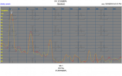
Interesting. This is at 2/3rds it's free air, so the "mass" mechanism is different.Here is a low frequency harmonic test. In this test it seems H2 is increased. The yellow trace is voltage feedback and the red trace has the "correction" coil added. I'll do a low frequency IM test in the morning. I'm a little baffled that IM can improve and HD not since the underlying mechanisms are the same. Maybe the one that has maximum impact on IM is improved but the nonlinearity that impacts harmonics isn't.
I note as well, you do no compensation that others used to control that rise in this area.
Do you have waveform capture? It would be good to see a voltage drive and diff signal at varying frequencies, as well as current drive/diff voltage vs freq.
Above resonance we are driving the cone mass, below it the forces required are automatically H2.
Jn
If one put a capacitor in series with the tweeter - will the distorsion reducing effect disappear?
//
I was thinking about it and am not sure yet. I will probably test it.
-------------------------------------
Regarding presence of 1 kHz difference tone in my tweeter test, asymmetric distortion, I do not assume it is a result of eddy currents, but I think it is a result of Kms stiffness asymmetry with displacement, in the tweeter.
Last edited:
Well, I just started to test and it seems like I bought a decent 10 dollar driver. The 2H is very low and only 3H shows. measured at 5cm and 100 db spl.
If I push it to 110 db spl I start to see more 2H and 3H ++ but it might be the microphone spl limit also. have to check.
100db spl

110db spl

Might have to get worse drivers....
-RNM
If I push it to 110 db spl I start to see more 2H and 3H ++ but it might be the microphone spl limit also. have to check.
100db spl
110db spl
Might have to get worse drivers....
-RNM
Last edited:
Thats my own issue as well. I have just stared at the amp all day. I am going to use a Hafler XL280. But getting to the parts/wires is not so much fun. I will eventually do it.
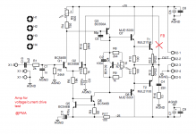
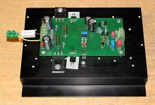
This is what I use for the test (modified old Sir Clive's). FB from out to R14 track was cut and FB is now on the yellow wire (photo). The resistor is the current sensing resistor for current drive.
Attachments
Well, I just started to test and it seems like I bought a decent 10 dollar driver. The 2H is very low and only 3H shows. measured at 5cm and 100 db spl.
If I push it to 110 db spl I start to see more 2H and 3H ++ but it might be the microphone spl limit also. have to check.
Might have to get worse drivers....
-RNM
Is it with any correction, or just a voltage drive?
Do you have 60Hz mains network?
")
This is what I use for the test (modified old Sir Clive's). FB from out to R14 track was cut and FB is now on the yellow wire (photo). The resistor is the current sensing resistor for current drive.
Thats a nice little circuit/amp. Easy to get at everything.

-RNM
Is it with any correction, or just a voltage drive?
Do you have 60Hz mains network?
just checking it first with volt drive... stock config.
yes 60Hz
-RNM
It's been my experience that the later (and higher power) LM****'sStarting with one of these: HiFi LM3886TF Mono 68W 4Ω Audio Power Amplifier Board AMP 50W/38W 8Ω Q5B5 191466724989 | eBay can make exploring dual coils much easier. Most assembled amps don't lend themselves to lifting parts and adding wires. Especilly if its an amp you care about. And this is incredibly cheap.
I think there is more research and exploration needed before really executing the concept.
are not the most stable circuits to begin with, let alone with
experimentation.
I would suggest :
https://www.mouser.com/datasheet/2/308/TCA0372-D-116057.pdf
FAR BETTER for experimentation ( assuming sufficient power for purpose)
We have to take care in the measurements to avoid excessive BL(x) as it quickly dominates everything, also there is a chance of canceling effects. With no Klippel data on a driver all we can do is try restrict excursion to less than Xmax/2 or so. Since Xmax specs are pretty arbitrary better err on the safe side. A way to estimate Xmax is playing a soft midrange tone and add adjustable DC (current drive for both) to offset the coil while looking at the level change of the SPL (terminal voltage is OK, too, provided temp rise is non-critical). Try keep level drop to a few percent max.
My test amp is a hybrid with an LM12 driven by an OPA134. Fortunately its pretty easy to tweak. Stability is not trivial in this configuration but can be attained and still have power to 80 KHz, even with the unusual feedback arrangement in this application.
If you follow the datasheet the LM3886 seems to be pretty stable even running motors on the other side of transformers. And they don't seem to break under duress.
If you follow the datasheet the LM3886 seems to be pretty stable even running motors on the other side of transformers. And they don't seem to break under duress.
+ 1 ^ 3 ....... even back to the LM1875My real-world experience with LM3886 stability was not good. Maybe motors do not care that much about possible HF components in the drive signal.
Data sheet stability is one thing ..........
Or :
" Maybe motors do not care that much about
possible HF components in the drive signal. "
I know you have good listening perception. Soon enough your findings will tempt you towards multi amp and line level crossover.I was thinking about it and am not sure yet. I will probably test it....
And yes, it will be worth the effort, no kidding.

Take 2. I think this is closer to what you are currently thinking. It does seem to work much better with a 10 dB reduction in the 1.1 KHz sidetone over voltage feedback. The 800 Hz tone seems unchanged. The level is reduced by about 6 dB which seems right. If this is right i'll do a more complete battery of tests. What to test for?
Pictures; circuit, "coil difference" feedback and voltage feedback for reference.
Maybe you also want that protection resistor if the feedback coli/path breaks - as mentioned before by JN.
How do one calculate R4?
//
If one put a capacitor in series with the tweeter - will the distorsion reducing effect disappear?
//
Once again to this, if I put a cap in series with the tweeter (SP1)
http://pmacura.cz/V_I_converter.GIF
there will be no DC feedback and amp output will travel to the supply rail. It would have to be a split feedback (DC x AC).
An 8 - 32 ohm resistor from amp output to R6 also help limit current delivery around resonance.... It would have to be a split feedback (DC x AC).
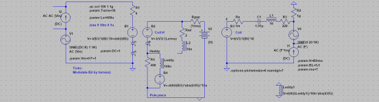
I am playing with a flux model which I think will help with the magnetic nonlinearity modeling.
Current in the voicecoil generates a static H-field (B2) which adds or subtracts from the H-field of the magnet (V2). The difference appears across Rgap which represents the permeability of the magnet. The current through it represents flux, from which Le and force are derived.
The magnet H establishes flux through Rgap. The coil H (B2) adds or subtracts from this flux, and the resulting Bl modulation results in distortion. This models reluctance force; if the voicecoil current were large enough, it would overcome the Bl of the magnet and be attracted to it rather than pushed away.
I'm pretty sure this is wrong in some way or I'm using the wrong terminology. I think H is analogous to voltage and flux/B is analogous to current.
For some reason I can't put dI eddies and coil velocity eddies in the same flux loop. B4 is my best attempt so far but it still doesn't work right. B4 represents a flux generated by the movement of an energized coil abs(I(V5)).
Leddy provides the resistive component of eddy currents shunting Le. However I can't get these eddies to provide damping to the cone at the same time.
Attachments
- Status
- Not open for further replies.
- Home
- Member Areas
- The Lounge
- John Curl's Blowtorch preamplifier part III