John I don't know if you get Absolute sound or not but the JC3 jr won phono stage of the year. Congratulations!
John I don't know if you get Absolute sound or not but the JC3 jr won phono stage of the year. Congratulations!
Awesome, John! Well done!
Cheers!
Howie
Looks like JN's or current feedback control can do a lot in reducing distortion. The velocity feedback however does not do enough to bother with.... 6dB on 2H and less on 3H and above harm.
-RNM
-RNM
Last edited:
....snip
I have updated my page
Proudove buzeni repro a zkresleni repro
4800+5000Hz plots show reduction of both harmonic and intermodulation odd distortion components under the current drive.
If one put a capacitor in series with the tweeter - will the distorsion reducing effect disappear?
//
Initial tests of coil feedback
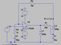
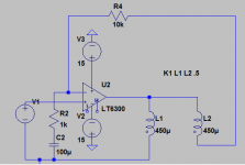
I managed to do some initial tests. The circuit I'm using is below. With no DC feedback it drifts to a rail so the DC feedback is necessary. The scheme seems to work pretty well.
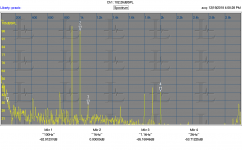
Per latest request these are two tone tests. First is voltage feedback, the second is using the second coil as the source per the drawing. The output of the coil in this application is about 8 dB less so the actual level is 8 dB higher. I compensated on the drive so both tests are at a measured 102 dB 1" from the center dome. The two tones are 900 Hz and 1 KHz.
In both cases the 100 Hz difference tone is lost in the mud. The 800 Hz and the 1.1 KHz tones are quite prominent. Unfortunately it seems the coil feedback makes them stronger than a hard voltage source.
What additional tests should I be doing?
I managed to do some initial tests. The circuit I'm using is below. With no DC feedback it drifts to a rail so the DC feedback is necessary. The scheme seems to work pretty well.
Per latest request these are two tone tests. First is voltage feedback, the second is using the second coil as the source per the drawing. The output of the coil in this application is about 8 dB less so the actual level is 8 dB higher. I compensated on the drive so both tests are at a measured 102 dB 1" from the center dome. The two tones are 900 Hz and 1 KHz.
In both cases the 100 Hz difference tone is lost in the mud. The 800 Hz and the 1.1 KHz tones are quite prominent. Unfortunately it seems the coil feedback makes them stronger than a hard voltage source.
What additional tests should I be doing?
Attachments
A very good thought and question. However, his amp plots show nada 1khz.If one put a capacitor in series with the tweeter - will the distorsion reducing effect disappear?
//
My suspicion is that the beat frequency is causing eddy dissipation.
As the sines temporally line up, the velocity hence eddy loss rises. When they are opposing, velocity hence eddy loss reduces. So the sum of the two frequencies is the reason. They are causing a 1 kHz eddy loss modulation.
That is why I mentioned earlier using the DVC set to look for this effect, the pickup coil will pull out the reactance, so the resistive voltage should be modulated at the 1khz rate.
Also, that is why I asked about the front plate and or pole piece being ferrite to eliminate the eddy dissipation.
Jn
Ps. Course, that's just speculation.😀
Last edited:
Demian, why did you put the 20 k between the coils. The intent is to subtract the emf's, that choice alters the design. Leaves pretty much nothing left after the cap shunt to ground, .7 hz break.I managed to do some initial tests. The circuit I'm using is below. With no DC feedback it drifts to a rail so the DC feedback is necessary. The scheme seems to work pretty well.
Per latest request these are two tone tests. First is voltage feedback, the second is using the second coil as the source per the drawing. The output of the coil in this application is about 8 dB less so the actual level is 8 dB higher. I compensated on the drive so both tests are at a measured 102 dB 1" from the center dome. The two tones are 900 Hz and 1 KHz.
In both cases the 100 Hz difference tone is lost in the mud. The 800 Hz and the 1.1 KHz tones are quite prominent. Unfortunately it seems the coil feedback makes them stronger than a hard voltage source.
What additional tests should I be doing?
As to the lack of 100 hz, if it's eddy generated, perhaps the frequencies are too low.
Ps. Why the 100 uf at the neg input?
Jn
Last edited:
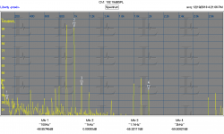
Take 2. I think this is closer to what you are currently thinking. It does seem to work much better with a 10 dB reduction in the 1.1 KHz sidetone over voltage feedback. The 800 Hz tone seems unchanged. The level is reduced by about 6 dB which seems right. If this is right i'll do a more complete battery of tests. What to test for?
Pictures; circuit, "coil difference" feedback and voltage feedback for reference.
Pictures; circuit, "coil difference" feedback and voltage feedback for reference.
Attachments

Demian,Take 2. I think this is closer to what you are currently thinking. It does seem to work much better with a 10 dB reduction in the 1.1 KHz sidetone over voltage feedback. The 800 Hz tone seems unchanged. The level is reduced by about 6 dB which seems right. If this is right i'll do a more complete battery of tests. What to test for?
Pictures; circuit, "coil difference" feedback and voltage feedback for reference.
In the coil diff, 800 and 1.2k are gone. Looks to be about 14 dB drop.
Fast work, very nice.
Jn
Oh, can you repeat the 40 hz 1 volt free air? There was good H2 and H3, it'd be great to see the actual measurement of the difference the drives make.
Last edited:
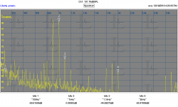
I mistaked the spur at 750 for 800 Hz. I wonder if there might be an optimum mix of the cancellation signal. This circuit is pretty simple to implement if you can get inside an amp. I spent more time getting the old test amp I used working right.
I mistaked the spur at 750 for 800 Hz. I wonder if there might be an optimum mix of the cancellation signal. This circuit is pretty simple to implement if you can get inside an amp. I spent more time getting the old test amp I used working right.
I'm still bummed out that H2 and H3 were unaffected. I wonder if it's because it's at the top end of the driver.
Oh, it would be great to see 40 and 500 or 1k, looking for Le(x) modulation of the hf signal given reasonable displacement into the 300 and 500 uh areas. I suspect my scheme will show good results there.
Jn
Last edited:
Its very possible those harmonics are cone artifacts. I did a quick response curve and it seems essentially unchanged. I need to do more careful setups before I post them. I can redo the LF harmonic measurements as well.
I can put the driver in a box soon as well but i want to finish useful data collection on the driver in "free air" first.
I can put the driver in a box soon as well but i want to finish useful data collection on the driver in "free air" first.
Excellent work. I look forward to more results, from you, Richard, and KSTR.Its very possible those harmonics are cone artifacts. I did a quick response curve and it seems essentially unchanged. I need to do more careful setups before I post them. I can redo the LF harmonic measurements as well.
I can put the driver in a box soon as well but i want to finish useful data collection on the driver in "free air" first.
I have to laugh, I now get advertisements for all kinds of pro midrange driver recone kits and speaker Litz flex lead on every web page I go to. Talk about your directed ads..I mean, just because I was pricing it out?? 😀
Jn
Starting with one of these: HiFi LM3886TF Mono 68W 4Ω Audio Power Amplifier Board AMP 50W/38W 8Ω Q5B5 191466724989 | eBay can make exploring dual coils much easier. Most assembled amps don't lend themselves to lifting parts and adding wires. Especilly if its an amp you care about. And this is incredibly cheap.
I think there is more research and exploration needed before really executing the concept.
I think there is more research and exploration needed before really executing the concept.
I mistaked the spur at 750 for 800 Hz. I wonder if there might be an optimum mix of the cancellation signal. This circuit is pretty simple to implement if you can get inside an amp. I spent more time getting the old test amp I used working right.
Thats my own issue as well. I have just stared at the amp all day. I am going to use a Hafler XL280. But getting to the parts/wires is not so much fun. I will eventually do it.
Then we can see how much my drivers are affected. I am using DVC which are wound on top of each other. We can see if the reduction is about the same as Demian's or what difference there might be. If there are any significant differences, i will show it here.
-RNM
Last edited:
- Status
- Not open for further replies.
- Home
- Member Areas
- The Lounge
- John Curl's Blowtorch preamplifier part III