MC1496 -- was gonna build a VNA using this chip but bought an HP3577a instead!
Good decision.
I don't estimate these Gilbert cells very high. Noisy and low IP at the same time.
I have that ADC finally running. It was a lot of software, so I wanted to do something
with bolts & nuts. I decided to build the delay line for my phase noise tester. Two of
the ADCs will later process the noise sidebands more downstream.
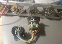
The delay line will be used to enforce phase quadrature between two mixer inputs.
That is done with 3 * 2 Coax relays, each 1-to-6 and many, many coax cables.
A coarse, middle & fine stage for use between 5 MHz and 100 MHz. I have collected
the relays over the years on ebay & flea markets. It turned out that 2 of them had TTL
drivers and both of these had defective bits

They were impossible to open in a gently way, so I filed a hole into the can and then
peeled it away. I hope the coils are still ok, I do not need the TTL drivers.
Cheers,
Gerhard
Attachments

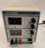
Any suggestions for a lab supply on tube heaters.
I like the adjustable metered supplies but looking for maybe other ideas.
Hash is usually the issue on audio apps. 4v to 13v needed.
Found a solution to my question.
B&K 1730 totally linear dual-range bench supply.
Perfect for heaters during prototype stage. Sets noise baseline for switchers later.
Attachments
RF Transmitters most certianly ARE DIY items. As well as receivers, and RF amplifiers.Yes, I was not condoning illegal operation but answering the point made that RF transmitters are not really DIY items. They are, but only for those who know what they are doing - which includes staying within the law. For almost everyone that means either fairly low power (almost zero power in the UK) or legitimate amateur radio. It is unlikely that a DIY transmitter for the FM broadcast band with significant power would be legal in almost any country.
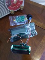
Stuff has been trickling in ....
The small module at the top is the broadband linear amp. It looks pretty nice, compact, decent construction, etc.
The sealed bag has the AD9850 DDS. Pretty barebones - what is in that bag, is what I got. No encoder, no pigtails for the onboard connectors. This is an observation, not a complaint. The price is certainly right, if it works. I don't have the correct connectors, so I'll have to hard wire to the board, or try to find some at one of the electronic shops up around our second house. I'm back at the office for a few days before I head back up there.
The third pic is the QRP Labs Si5351 frequency synthesizer. It is almost the same size as the DDS. The DDS is a bit larger because of the pushbutton switches along the bottom. The Si5351 board gets by with two buttons on the back of its mainboard. I've played some with the programming on the QRP Labs frequency synthesizer, and I'm pretty impressed with that aspect of the device. It's really a nice piece, the Si5351 notwithstanding.
Its turned pretty cold here, so even though I am back for a few days, I don't anticipate doing much work out in the shack.
Win W5JAG
Attachments
Last edited:
Check this out, Hams:
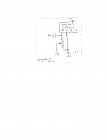
Ordinary SA602 (DIP) mixer chip, 6 volts B+, wired in the typical manner - single ended input, and output taken single ended through one of the two output pins; the unused output pin is floating, EXCEPT a 1 meg trim pot is connected between the two input pins, with the wiper to ground.
9 MHz goes to one input pin, the other pin goes to ground through an .01 cap.
LO goes to pin 6.
The FeelTech DDS is used as the signal generator.
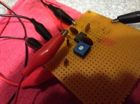
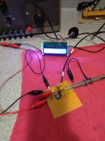
First pic is the test setup on a piece of scrap perf ( sorry for the lousy pics ).
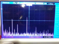
Third pic plainly shows the 9 MHz simulated SG-9 input, the 23 MHz LO, and the 14 MHz mix product.
Center pic shows how adjustment of the 1M trim pot has brought the 14 MHz signal up 7 dB, and nulled the LO port. The DSO is counting the desired output signal.
So, it does look like there is merit in pursuing the idea that the Si5351 spurs can be nulled sufficiently to make a clean TX with ordinary bandpass filtering of the mixer output.
I expect that balancing the output should null the 9 MHz input to some degree, but I'm not sure that is even necessary - it is easily filtered out.
A caveat: it takes a very low level of LO to do this: I have the FeelTech set at 0.3 volts and then that is fed through a 22 pf capacitor to the LO port, so conversion gain would suck, but I don't see that as a big deal in a TX strip. Gain can be made up later.
Win W5JAG
Ordinary SA602 (DIP) mixer chip, 6 volts B+, wired in the typical manner - single ended input, and output taken single ended through one of the two output pins; the unused output pin is floating, EXCEPT a 1 meg trim pot is connected between the two input pins, with the wiper to ground.
9 MHz goes to one input pin, the other pin goes to ground through an .01 cap.
LO goes to pin 6.
The FeelTech DDS is used as the signal generator.
First pic is the test setup on a piece of scrap perf ( sorry for the lousy pics ).
Third pic plainly shows the 9 MHz simulated SG-9 input, the 23 MHz LO, and the 14 MHz mix product.
Center pic shows how adjustment of the 1M trim pot has brought the 14 MHz signal up 7 dB, and nulled the LO port. The DSO is counting the desired output signal.
So, it does look like there is merit in pursuing the idea that the Si5351 spurs can be nulled sufficiently to make a clean TX with ordinary bandpass filtering of the mixer output.
I expect that balancing the output should null the 9 MHz input to some degree, but I'm not sure that is even necessary - it is easily filtered out.
A caveat: it takes a very low level of LO to do this: I have the FeelTech set at 0.3 volts and then that is fed through a 22 pf capacitor to the LO port, so conversion gain would suck, but I don't see that as a big deal in a TX strip. Gain can be made up later.
Win W5JAG
Attachments
Not my idea - I saw it while looking at some other homebrew designs, but can't recall who to attribute it to.
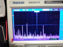
When I first tried it, I had the LO going into the RF inputs, and was surprised to see that the adjustment nulled the LO port rather than the input. So I switched the ports and put the LO on pin 6 where it would normally go, and the results can be seen in the terrible center picture - the LO pretty much went away, and the 23 and 9 mix products at 14 and 32 came right up to ( near ) equal amplitude, although it does show some IMD artifacts.
This is not in any of the documentation AFAIK, or any of the many articles about using the '602, but at first glance it looks like it could be a neat trick to take advantage of. It was really cold in the shack so I didn't play with it at all - just grabbed a couple of shots and called it a night.
Win W5JAG
Attachments
Last edited:
RF stuff??????
I went on a road trip to Florida last week, and of course stopped in at ESRC for a big box full of vacuum tubes.
I also went black Friday shopping at Skycraft Surplus while the women slugged it out in the malls. Got several precut 1/8 inch aluminum top plates for big amp chassis and a BIG box full of assorted SMD parts, most on reels, all for $30.
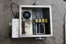
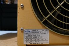
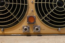
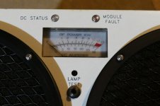
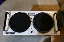
The RF stuff however was already waiting for me in a friends warehouse where it has been for a few years. I didn't have room for the 10 KW water cooled HF ISM amp, but I did drag back a 1 kilowatt amp that covers 400 to 450 MHz. It is 5 RU tall by 24 inches deep and weighs in at over 100 pounds....fun getting it out of the car and down into the basement. There was another cube with a large ceramic tube and a PI network that found its way into my car along with a 30 dB attenuator rated for 300 watts. 432 MHz EME anyone?
I went on a road trip to Florida last week, and of course stopped in at ESRC for a big box full of vacuum tubes.
I also went black Friday shopping at Skycraft Surplus while the women slugged it out in the malls. Got several precut 1/8 inch aluminum top plates for big amp chassis and a BIG box full of assorted SMD parts, most on reels, all for $30.
The RF stuff however was already waiting for me in a friends warehouse where it has been for a few years. I didn't have room for the 10 KW water cooled HF ISM amp, but I did drag back a 1 kilowatt amp that covers 400 to 450 MHz. It is 5 RU tall by 24 inches deep and weighs in at over 100 pounds....fun getting it out of the car and down into the basement. There was another cube with a large ceramic tube and a PI network that found its way into my car along with a 30 dB attenuator rated for 300 watts. 432 MHz EME anyone?
Attachments
.... 432 MHz EME anyone?
I'm in. With Gerhard, that would make three, enough for an intercontinental round table ...
I have an FT-847 sitting in a box here at the office, that is not being used for anything. I'll need a longish lead time, though, for the antennas, etc.
I gave away / sold all my 4XC250 stuff, although I did find some Johnson silver sockets, and some 4X150's when I was scouring the shack for a prefab FM tuner a couple of summers ago.
Considering all the drama over just a simple HF rig, which is still nowhere close to being finished, maybe giving away the VHF / UHF parts was for the best ...

Win W5JAG
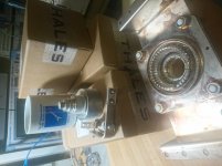
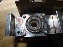
I have found that stuff in the basement this week:
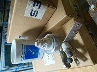
One Coax socket
3 pcs. TH316 tubes, boxes still unopened (all but one, I was curious)
I have no idea what the spark gap is for.
The used coffee mug happened to be still on the table from
earlier this day; it is on-topic by pure co-incidence.
A friend of mine is really active; with his new antenna, 10W
and a 4 element should be enough for 2way qso.
< http://dl7apv.darc.de/Neue Antennen/Neue Antennen.htm >
Attachments
Last edited:
...A friend of mine is really active; with his new antenna, 10W
and a 4 element should be enough for 2way qso.
< http://dl7apv.darc.de/Neue Antennen/Neue Antennen.htm >
Wow. That array should be on magazine covers.
Win W5JAG
Yeah, 1500 watts into that array could push the moon out of orbit!
The antenna array has 33.6 dB gain over a dipole and a dipole is 2.1 dBi, so the array has 35.7 dBi. Feed that 1500 watts and you have 5.57 MEGAWATTS of ERP. The maximum ERP allowed for TV broadcasting in the USA is 1 megawatt.
The antenna array has 33.6 dB gain over a dipole and a dipole is 2.1 dBi, so the array has 35.7 dBi. Feed that 1500 watts and you have 5.57 MEGAWATTS of ERP. The maximum ERP allowed for TV broadcasting in the USA is 1 megawatt.
So, on a hunch, over the break, I ordered a new microprocessor chip for the QRP Labs synthesizer, and this seems to have made some improvement in the output spectrum.
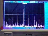
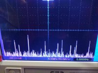
Below are FFT captures at 23.280 MHz and 59.280 Mhz, representing the middle of the 20 meter phone band, for a 9 and 45 MHz IF, respectively. Why the Si5351 device would be sensitive to the quality of the microprocessor I do not know, but it appears possible this can influence the quality of the output spectrum, as it certainly caused me much grief with the other synthesizer.
Both of the outputs below are probably usable with a simple single ended mixer and simple filtering, but, as before, if the output spectrum is at, or close to ( within a few hundred kilohertz - as is likely to be the case ), 5 MHz or a multiple thereof, the output spectrum is saturated with close in, high amplitude spurs, and at least a singly balanced mixer to cancel the LO would be mandatory, imo.
I have not tried the AD9850 DDS, and it does not appear it will be necessary to do so.
Happy New Year!
Win W5JAG
Attachments
Last edited:
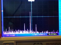
A quick test setup, using the SA602 in the singly balanced setup; 10 dB ish attenuation on the Si5351 LO.
The tallest peak is the 14.3 MHz mix product. Looks like it will work at first glance.
Haven't tried to optimize the LO drive.
Win W5JAG
The tallest peak is the 14.3 MHz mix product. Looks like it will work at first glance.
Haven't tried to optimize the LO drive.
Win W5JAG
Attachments
So, unless someone with more RF experience than myself is seeing something that I am not, then, for a 20 meter rig, it looks like those rogue spurs seen at 16 MHz and 10 MHz, and their mixing products ( which move around as the device is tuned ) in the S15351 output spectrum, are adequately cancelled in the SA602 output spectrum, so as to make the SA602 usable as a low level TX mixer in the singly balanced configuration, even though it is designed and marketed as an RX mixer. (Holy run on sentence, Batman).
I think there is more improvement to be had by optimizing the LO drive, and, in any event, LO level will have to be tweaked for the AD831 RX mixer as well. The way this thing has gone down, I totally expect that the optimal LO drive point will be different for both devices.
Interestingly, it looks like the 59 MHz ish output, which works for a 6 meter rig with a 9 MHz IF, should be acceptable to use with the simple HEP MOSFET mixer already on the board and working, should I decide to go with 6 meters, which is still a distinct possibility, the drawback being that a 6 meter rig that would need to be in service by early Spring for sporadic E season. At the glacial pace this project has proceeded, that may be unrealistic.
Win W5JAG
- Home
- Member Areas
- The Lounge
- No RF gear here?