Good,
why not try a new pot first, costs pennies and nothing to loose.
Alan
Agreed. My tip would be to make it a 25 turn unit to make biasing easy.
I will check that tommorow and get back to you.
Well something strange, when I measure across R7, I measure 3.3K...on the other side its 10K.
I unsoldered R7 and check it and it measured 10K. But back in the circuit its remain at 3.3K. What can cause this ?
Well something strange, when I measure across R7, I measure 3.3K...on the other side its 10K.
I unsoldered R7 and check it and it measured 10K. But back in the circuit its remain at 3.3K. What can cause this ?
Hi Sidsmith,
Sorry, this is getting a bit 'circular'. I have been over the previous posts and unfortunately given the measurements you have it is difficult to draw a conclusion.
Last time you had a reading of zero ohms from ground to Gate of Q2 ( ... then from ground to G (Q2) = 0r )
Advice is still the same, remove the faulty board and inspect it for shorts, solder blobs etc. You could post a picture of the back of the board for us to see too?
After that it is guess work, start by checking Q2 and Q1 are Ok...
There are a couple of Youtube tutorials on how to do a simple test on a Mosfet transistor you could look at and so on.
Alan
I just received my kit but the screws and nuts were not included with the chassis. Would someone please tell me exactly what sizes of screws and nuts I need and in what quantity? It would be greatly appreciated as this is the only thing preventing me from assembling my amp. I hope this is the right thread for this question.
Thank you
Thank you
Hi ptol,
The hardware for the kit should be included with the package containing the boards and parts, not in the chassis kit. Sorry if it is missing.
If it is not there have a look at post #6975 here; Amp Camp Amp - ACA
It should get you going.
Alan
The hardware for the kit should be included with the package containing the boards and parts, not in the chassis kit. Sorry if it is missing.
If it is not there have a look at post #6975 here; Amp Camp Amp - ACA
It should get you going.
Alan
Hi ptol,
The hardware for the kit should be included with the package containing the boards and parts, not in the chassis kit. Sorry if it is missing.
If it is not there have a look at post #6975 here; Amp Camp Amp - ACA
It should get you going.
Alan
When it came to spare fender, or (as per local parlance where I'm from) "mudguard", washers I struggled to find something workable with a circular outer diameter. I wanted a washer sufficiently large to spread the bolting force across the MOSFET to achieve good thermal contact, without needing to risk damage from screwing it down too hard.
After a bit of trial and error, I ended up going square:
Square Washers 304-A2 Stainless-Steel
Specifically, an M3 ID and 16 mm square outer. Just an alternative to bear in mind.
Mondo coolio!
Had no idea square washers existed.
Will try to track some of these of these down.
Gary - are you measuring the bias as shown in the guide and it’s always reading the same thing? Do you have an autoranging meter or one where you have to choose the range? If the latter set to DC volts 200.
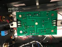
I just completed the ACA build with some new parts. I was able to set the bias to 12v on both channels. However, there's audio output on the left channel only. I used my DMM to test continuity for all the wires I soldered. All passed. I removed the rail and confirmed none of the wires I soldered to the board were touching the heatsink. I checked the wiring against the wiring diagram and all appears to be in order. Given my complete lack of soldering skills it's likely the problem is down to a bad solder. I'm just not sure how to proceed at this point. I'm hoping someone can point me in the right direction. Again, I know the soldering is terrible. Thanks.
Attachments
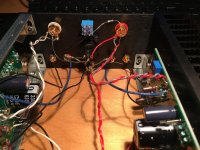
I just completed the ACA build with some new parts. I was able to set the bias to 12v on both channels. However, there's audio output on the left channel only. I used my DMM to test continuity for all the wires I soldered. All passed. I removed the rail and confirmed none of the wires I soldered to the board were touching the heatsink. I checked the wiring against the wiring diagram and all appears to be in order. Given my complete lack of soldering skills it's likely the problem is down to a bad solder. I'm just not sure how to proceed at this point. I'm hoping someone can point me in the right direction. Again, I know the soldering is terrible. Thanks.
To coin a well read phrase, post a series of well lit, in focus shots of the board on both sides. Those with the smarts and experience will very probably offer you good guidance.
EDIT: I wouldn't be surprised if the underside of the PCB tells the story.
Have you checked installed component resistance from the relevant step on the build guide? Could be something to tick off while you wait.
Last edited:
I was able to set the bias to 12v on both channels. However, there's audio output on the left channel only. I used my DMM to test continuity for all the wires I soldered. All passed. I removed the rail and confirmed none of the wires I soldered to the board were touching the heatsink. I checked the wiring against the wiring diagram and all appears to be in order. Given my complete lack of soldering skills it's likely the problem is down to a bad solder. I'm just not sure how to proceed at this point. I'm hoping someone can point me in the right direction. Again, I know the soldering is terrible. Thanks.
Gary,
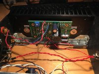
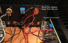
First thing is move the resistor shown in the picture away from the nut. If it touches it it will short your input and you will get no sound. And re-solder the speaker connection.
If that does not fix it, do both amplifier heatsinks get hot after a few minutes of being switched on?
Then the way forward is to remove the faulty board and take pictures so we can see it too as astromo says.
Now we can see the top of the board, I still suspect a poor solder joint.
As you get the 12 volt 'bias' ok, I would think the large capacitor C1 is not soldered in correctly?
There is a troubleshooting section (Step 56) in the build guide that gives typical resistance and voltage readings. Amp Camp Amp V1.6 Build Guide - diyAudio Guides
But I think that comes next if re-soldering does not fix it for you...
Alan
Attachments
Last edited:
I plan to solder a ceramic capacitor to the power switch terminals to remove the pop-up sound when switching ACA on or off. Any recommendation for the value of the ceramic cap?
The ACA does make a 'thruump' at switch on (and off). That is normal as C1 charges.
Assuming you are using the power 'brick' to supply your ACA, there is little point in adding a cap of any value to the power switch?
Alan
Gary,
First thing is move the resistor shown in the picture away from the nut. If it touches it it will short your input and you will get no sound. And re-solder the speaker connection.
If that does not fix it, do both amplifier heatsinks get hot after a few minutes of being switched on?
Then the way forward is to remove the faulty board and take pictures so we can see it too as astromo says.
Now we can see the top of the board, I still suspect a poor solder joint.
As you get the 12 volt 'bias' ok, I would think the large capacitor C1 is not soldered in correctly?
There is a troubleshooting section (Step 56) in the build guide that gives typical resistance and voltage readings. Amp Camp Amp V1.6 Build Guide - diyAudio Guides
But I think that comes next if re-soldering does not fix it for you...
Alan
Hi ALan,
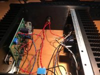
Thanks for the response. I did resolder that connection and moved the resisdtor away from the nut. The issue is still not solved. I noted I could hear music playing faintly through the right channel along with some very faint fuzz. I did not hear a turnoff thump as I do in the left channel. I also resoldered the connections for the large capacitor C1. I again confirmed no wires are touching the heatsink. I'll begin the troubleshooting as you suggest. I see that another builder, JP14 is having an issue that sounds very similar to mine.
Thanks again.
Attachments
... thanks for the response. I did resolder that connection and moved the resisdtor away from the nut. The issue is still not solved. I noted I could hear music playing faintly through the right channel along with some very faint fuzz. I did not hear a turnoff thump as I do in the left channel. I also resoldered the connections for the large capacitor C1. I again confirmed no wires are touching the heatsink. I'll begin the troubleshooting as you suggest.
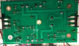
Hi garyalex,
As you say not the best soldering job!
If you look closely there are a couple of holes at R12 and Q3. You have to ensure the component leg comes through the board then soldered. Also there are some joints where the solder has not flowed. Quite a few possible 'cold' or 'dry' joints.
Start by re-soldering every connection and checking all the legs are fully through the holes.
I would suggest you leave the iron on the joint (the leg and the pad) a little longer before applying the solder, then it will flow better. A good sign is that you get a cone of solder round the leg on the front as well as the back of the board. If it is blobby or not through the board, do it again. Practice ehy?
Warnings now. Do not switch on until you remount the board onto the heatsink, you will pop the Q1 and Q2 MosFets... When you re-fit it make sure the thermal pads and faces of Q1 and Q2 are spotlessly clean.
Alan
Attachments
Last edited:
When you re-fit it make sure the thermal pads and faces of Q1 and Q2 are spotlessly clean.
Alan, what would you suggest as a sensible plan to realise the above piece of advice?
Alan, what would you suggest as a sensible plan to realise the above piece of advice?
Nothing special, soft cloth even a finger. It is just a warning to make sure nothing is trapped between the pad and transistor face.
With so much 'splatter' and odd solder blobs about, it would be easy to trap one between the two.
The thermal pad is easily pierced by debris and then the electrical insulation it gives is lost and the transistor can short to the heatsink... errr it has happened before when people are eager to try out the fixes.
Hi,
 Late to the game as usual. Thanks to Alan for sleuthing through this one, he is being so gracious with his time and efforts!
Gary,
Looking through your pictures, I am wondering if you made sure that the black binding posts (like the red binding posts) also has a black plastic insulating spacer? It's unclear in the pictures due to the black on black contrast with the back panel. If there isn't an insulating spacer, then your speaker output signal will be shorted.
Hope you get it resolved! If you are in the U.S., I'll be happy to take a look, clean up/resolder the boards, etc...in exchange for shipping costs. But that wouldn't be very instructional for you and one of the goals here with the ACA kit is to make it a learning/iterative process.
Best,
Anand.
Late to the game as usual. Thanks to Alan for sleuthing through this one, he is being so gracious with his time and efforts! Gary,
Looking through your pictures, I am wondering if you made sure that the black binding posts (like the red binding posts) also has a black plastic insulating spacer? It's unclear in the pictures due to the black on black contrast with the back panel. If there isn't an insulating spacer, then your speaker output signal will be shorted.
Hope you get it resolved! If you are in the U.S., I'll be happy to take a look, clean up/resolder the boards, etc...in exchange for shipping costs. But that wouldn't be very instructional for you and one of the goals here with the ACA kit is to make it a learning/iterative process.
Best,
Anand.
Hi garyalex,
As you say not the best soldering job!
If you look closely there are a couple of holes at R12 and Q3. You have to ensure the component leg comes through the board then soldered. Also there are some joints where the solder has not flowed. Quite a few possible 'cold' or 'dry' joints.
Start by re-soldering every connection and checking all the legs are fully through the holes.
I would suggest you leave the iron on the joint (the leg and the pad) a little longer before applying the solder, then it will flow better. A good sign is that you get a cone of solder round the leg on the front as well as the back of the board. If it is blobby or not through the board, do it again. Practice ehy?
Warnings now. Do not switch on until you remount the board onto the heatsink, you will pop the Q1 and Q2 MosFets... When you re-fit it make sure the thermal pads and faces of Q1 and Q2 are spotlessly clean.
Alan
Hi Alan,
Thanks very much for the help. I've a board on which I can practise before trying to clean up the mess I made. I had some concerns about leaving the iron on components too long, thus damaging the part. I'll do as you suggest and have at it again.
Thanks - Gary
- Home
- The diyAudio Store
- Amp Camp Amp Kit 1.6/1.8