Albert, let's peel this back one step at a time. You have DC at the output, so that has to be fixed first. Replacing the power supply without knowing that it is defective may just change nothing: still DC at the output. That has to be diagnosed and fixed first, everything else is secondary.
How much DC is on the output? Did you measure it, do you have a multimeter? If so, measure all the DC supply voltages to see if they are as advertised. Report back here and we take it from there.
Do you have a schematic?
I also think you should open a separate thread on getting your preamp up and running as it should.
Jan
You have a great story here. I appreciate the well written and explained question too. It is also reassuring the original manufacturer is able help with this. Lastly, I will add that even though you state yourself to be a newbie, you are quite the exception to what I expected to read in your post.
Having said all this, I personally cannot give the answers that you need, but rest assured that there will be comprehensive answers to follow. I too, would like to know if the SR would be applicable to other circuits. It seems to me that better power supply performance can only mean better performance in general. Maybe equivalent in some ways to decent power conditioners available out there.
I eagerly await the advice to follow here.
Thanks Jan. Yes, a new thread will probably be best. I assume under "analog line level". I will open one later today or in the next few days, when I have some more details to post.
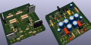
P-A: Good to hear that the LM723 is very quiet. I hope the design is done well. At the time it was the reference preamp from Jeff Rowland, so you would expect that they went the extra bit to ensure it was done properly. For as far as I can see all the parts used were good quality but I am not sure yet if they included the Cref capacitor that is needed to get it that low (if I read the datasheet correctly). I can't see it on the component side of the board but it might be hidden underneath, or I have not looked properly.
Ixnay: Thanks for the compliment! I think of myself as a noob, mainly because I don't know what I am doing")
I have built a few amps over the last 9 years or so (a.o. B1, Aleph J, J2 and recently I was a lucky winner of a VFet lottery amp that now plays in my bedroom), but so far most has been by the process of "painting by numbers" as I like to call it. I think "assemble" rather than "build" is the appropriate verb. As long as everything works, I am fine. It is when they don't that I get stuck.
Physical disability limits the work I can do unassisted, so I tend to think about things a lot more than try them out by building them. I should spend more time learning LTSpice to gain a better understanding of how systems work! If only the learning curve were less steep
I am slowly starting to understand a bit more, and have designed a few simple pcb's using KiCad for arduino and other things. But that was mostly for digital things, which given my software background I understand without thinking. This whole analog world is new and foreign to me!
After reading in another post that they seem to be supplying real parts, not fakes, I spent a couple of $ and ordered 10 x LM723 and 10 x TIP3055 from shenzhenYida store on Aliexpress. After I have figured out the schematic of the Consummate power supply, it will give me an idea how to build a test power supply. I assume the pre-regulator (LM317) that can be used for the SR, would be suitable for this as well and could help with the lower PSRR? It will be interesting to see if I hear any difference between different power supplies. Probably best to try this stuff on a diy BA3 preamp first! But, before that, I would like to get my Consummate working again.
P-A: Good to hear that the LM723 is very quiet. I hope the design is done well. At the time it was the reference preamp from Jeff Rowland, so you would expect that they went the extra bit to ensure it was done properly. For as far as I can see all the parts used were good quality but I am not sure yet if they included the Cref capacitor that is needed to get it that low (if I read the datasheet correctly). I can't see it on the component side of the board but it might be hidden underneath, or I have not looked properly.
Ixnay: Thanks for the compliment! I think of myself as a noob, mainly because I don't know what I am doing
I have built a few amps over the last 9 years or so (a.o. B1, Aleph J, J2 and recently I was a lucky winner of a VFet lottery amp that now plays in my bedroom), but so far most has been by the process of "painting by numbers" as I like to call it. I think "assemble" rather than "build" is the appropriate verb. As long as everything works, I am fine. It is when they don't that I get stuck.
Physical disability limits the work I can do unassisted, so I tend to think about things a lot more than try them out by building them. I should spend more time learning LTSpice to gain a better understanding of how systems work! If only the learning curve were less steep
I am slowly starting to understand a bit more, and have designed a few simple pcb's using KiCad for arduino and other things. But that was mostly for digital things, which given my software background I understand without thinking. This whole analog world is new and foreign to me!
After reading in another post that they seem to be supplying real parts, not fakes, I spent a couple of $ and ordered 10 x LM723 and 10 x TIP3055 from shenzhenYida store on Aliexpress. After I have figured out the schematic of the Consummate power supply, it will give me an idea how to build a test power supply. I assume the pre-regulator (LM317) that can be used for the SR, would be suitable for this as well and could help with the lower PSRR? It will be interesting to see if I hear any difference between different power supplies. Probably best to try this stuff on a diy BA3 preamp first! But, before that, I would like to get my Consummate working again.
Adjusting Bias Current
Would like to try some of Walt Jung's lower noise reference voltages on my V2.2 boards.
Can someone verify the resistor that sets bias current is R5 Pos / R12 Neg ?
Also - is this formula for calculating resistor value correct ?
R = ( Vout - V ref ) / (bias current in ma. x 1000 )
Would like to try some of Walt Jung's lower noise reference voltages on my V2.2 boards.
Can someone verify the resistor that sets bias current is R5 Pos / R12 Neg ?
Also - is this formula for calculating resistor value correct ?
R = ( Vout - V ref ) / (bias current in ma. x 1000 )
Attachments
in one of the articles describing SuperRegulator, it states, that a shunt resistor to ground at regulator`s output can serve as a form of a shunt voltage regulator in case of reactive load.
I almost finished integrating 2,5A/ 18V superreg into a JLH 1996 amplifier.
The power transistors of JLH are most linear at 2,3A, and i have some 200mA to play with a shunt resistor. 100mA at 18V dissipates around 2 Watts, so 5Watt non-inductive wirewounds from Mills could do fine here.
Should they though?
Would a e.g. 100 mA shunt current help the superreg to deal with back EMF of a speaker ?
Below is my 70x70 mm pcb project, with non-inductive resistors in feedback loops for both superreg and JLH, and bigger very high-temperature electrolytics, and additional bypass foil capacitor for zener diode in superreg (lower part). The last thing that bothers me are the vertical resistors crossing the legs of upper power transistors (180R shunts).
Also: i added a shunt 4,7k resistor at the gates of power transistors of superreg (where input CCS meets the output of AD797), non-inductive carbon-comps - would that help somehow to speed up the regulator?
Attachments
Last edited:
thank you. I leave the big shunts out and spare some $$ on Mills there.
i drew additional long thin trace from the point of regulation, i.e. input leg of JLH power transistor. On this trace i planned place for either a wire link or some 0R22-0R47 resistor.
At the end of this trace i placed the V+ of AD797 and lm329, and stabilizing output capacitor (https://www.vishay.com/docs/28465/190rtl.pdf).
I chose those Vishays mainly beacuse of their high temperature resistance (6000h at 125C),
At the bottom of ad797 i put additional 15uF mlcc, soldered directly across op amp`s legs.
both 100uF/50V from Vishay, and 15uF mlcc have very low ESR and impedance, and are effectively parallel.
Considering the output stability with these very low impedance caps, i decided to controll it with a resistor, and not to rely on the ESR of the capacitors.
what would be the best routing of the V+ trace? (> means trace, // a pour for parallel elements)
pointVreg>>0,47R>100uF elco>0,22R>15uF mlcc // AD797 // lm329 ?

>> It's not ideal, but few things are in life ;-)
True, but if ideal is within reach, I can skip straight to ideal. Would this mean separate bridge rectifier for each secondary winding and NOT what's shown in #2511?
Like a pair of these:
LT4320 ideal diode rectifier board from Pineapple Electronics on Tindie
?
True, but if ideal is within reach, I can skip straight to ideal. Would this mean separate bridge rectifier for each secondary winding and NOT what's shown in #2511?
Like a pair of these:
LT4320 ideal diode rectifier board from Pineapple Electronics on Tindie
?
What you need is two separate rectified/reservoir cap raw DC voltages that do not share a common ground. This can be two separate secondaries with bridges, or two separate secondaries with mid taps and pairs of diodes. Just your 'normal' setup but then two times.
The 'ideal rectifier' has only a very small advantage, it lowers the voltage loss by about 0.5V which is hardly worth it.
Jan
The 'ideal rectifier' has only a very small advantage, it lowers the voltage loss by about 0.5V which is hardly worth it.
Jan
I will be using a fast recovery bridge diode with a smoothing cap to feed the superReg to get about 500mA of power. What is the recommended type and size of smoothing cap?
Are there things like low ESR or certain types like Oscon to best use? Large film cap?
Thanks!
Are there things like low ESR or certain types like Oscon to best use? Large film cap?
Thanks!
Last edited:
Do you mean the cap that is fed by the rectifier bridge?
Don't spend a lot of money there, just any electrolytic will do.
It's the superreg that adds the 'quality' to the supply.
Low ESR is good in that position as it has the lowest ripple.
For 500mA, 4700uF gives only a few 100 mV ripple.
Film cap is a waste of money.
Jan
Don't spend a lot of money there, just any electrolytic will do.
It's the superreg that adds the 'quality' to the supply.
Low ESR is good in that position as it has the lowest ripple.
For 500mA, 4700uF gives only a few 100 mV ripple.
Film cap is a waste of money.
Jan
Last edited:
Is there a preferred type of power transformer for the rectifier circuit ?
I have read in a statement by John Curl that the typically wound Toroid is not good for low power circuits due to capacitive coupling of power line noise. Best to use R-core or EI core.
But what type EI core: split bobbin or the cheaper single bobbin?
Does it matter for the Superreg?
I have read in a statement by John Curl that the typically wound Toroid is not good for low power circuits due to capacitive coupling of power line noise. Best to use R-core or EI core.
But what type EI core: split bobbin or the cheaper single bobbin?
Does it matter for the Superreg?
- Home
- The diyAudio Store
- Super Regulator