Hi All,
I am going through H frame subwoofer design by Martin J. King. (PDF attached)
Please see the attached images also.
What does he mean by L(effective) & R(effective) ??
Can anyone help me understand please??
All I need to know is an ideal H frame dimensions for height, width, and depth(front depth and rear depth) for a 15" driver. Lets say Crossover is at 100 hz.
Thanks a lot in advance,
AudfrkNaveen
Attachments
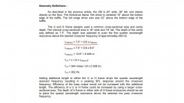

He wants the length to be shorter than c/4(100Hz). If "c" means 1125 fps, then the tunnel length should be shorter than 33.75". This keeps any tunnel 1/4 wave resonance far and away from your 100 Hz crossover frequency, while adding distance between the front and back wave of the driver. This distance is an improvement over simply putting the 15" driver on a reasonably wide baffle board, by rearranging the geometry form - without getting into trouble from resonant peaks.
I have the same crossover frequency, only I'm using 18" drivers. I've yet to construct my "U" tunnels, as I'm unsure if the baffle matching material I have on hand is enough, or if I want to use it for another set, or... I've got a couple large boards of this stuff stashed under my bed, so I'm "sleeping on it"!
I have the same crossover frequency, only I'm using 18" drivers. I've yet to construct my "U" tunnels, as I'm unsure if the baffle matching material I have on hand is enough, or if I want to use it for another set, or... I've got a couple large boards of this stuff stashed under my bed, so I'm "sleeping on it"!
The "r" stands for radius, hence it's "effective" because the cavity is rectangular. I'm not sure whether this calculator may be useful Cavity Resonance
All I need to know is an ideal H frame dimensions for height, width, and depth(front depth and rear depth) for a 15" driver. Lets say Crossover is at 100 hz.
Like many things in audio, there is no "ideal" anything. What you have are a set of tradeoffs in terms of various parameters. It's better to learn about the relationships involved, and then you can make your own decisions about what is best for YOU.
An H-frame typically has equal length "sides" (front side and back side tunnel depth) so that the output is essentially the same from both front and rear. This is valid at low frequencies (e.g. below 100Hz) where the subwoofer will be used.
I call an H-frame a subwoofer, because a standing wave wills set up in the front and rear tunnels. This creates a series of peaks and dips. Only the lowest of these are of any concern to the design. You cannot really use the subwoofer the frequency where the response starts to fall into the first dip. The dip is usually too deep to EQ, so this limits the use to lower frequencies, making it a subwoofer type application.
Describing the frequency response that you would measure at the plane of the tunnel mouth, at very low frequencies you get the typically 6dB/oct sloped response of a dipole. A you go up in frequency you will eventually reach a peak - this is a consequence of the tunnel resonance. The Q (sharpness) of this peak is a function of the aspect ratio of the tunnel. The more narrow and long the tunnel the higher the Q. The more shallow and broad the tunnel, the lower the Q. Martin King's dimensions were convenient for him in incorporating the peak into the crossover. He chose (or perhaps it was just luck) dimensions that resulted in a modest Q peak. When you make the tunnel opening small compared to the depth you can get a very sharp peak that is very difficult to EQ out, and in that case you are limited to using the subwoofer below the peak frequency, e.g. Fmax < 0.7*Fpeak. I prefer to use a low aspect ratio, that is make the opening large compared to the depth. This keeps the Q low enough that you can EQ it out and with an H-frame you have more or less the same peak at both front and rear. Thus, with some EQ the low-aspect H-frame can be used to and even ABOVE the peak, and it is the DIP that can be incorporated into the crossover.
Given what I just said above, you can make the length of the H-frame longer than what is typically seen. I have used a 1m long H-frame with good success, and this can be used to almost 150Hz. But you have to make it at least as wide as it is deep. Thus the tunnel is 0.5m wide as well, and 0.5m high. That is large, but it can accommodate even the largest drivers (21" for example). Using a smaller driver is no problem.
So, really the choice is "how large" an H-frame can you tolerate? This will determine the length, and then the width and height from the length. The longer you make the H-frame, the less low-frequency loss you will have. But keep in mind that if your room is also not long enough to fit at least a half wavelength at a given frequency it will attenuate dipole response at the frequency. So unless you have a pretty large room, a large H-frame is just not going to help you much with the low bass. Instead, use a closed box below 80Hz and only use dipole down to that frequency. In that case, no H-frame is necessary, in fact I have used 15" drivers without any baffle (nude) down to 80-100Hz. So the listening space must also be considered in the design choices.
Finally, there is the driver and amplifier. If you are planning to use a driver with a low or modest Qts (e.g. less than 0.4-0.5) than you will need to EQ the low end "up". For an H-frame, the response you get will be the driver's free air response PLUS the response of the H-frame. So with lower Qts drivers the driver's own response will "droop" around Fs and this might mean another 6-10dB of loss at the lowest frequencies. You will need active EQ to boost that up plus a LOT of amplifier power compared to using the same driver in a closed box. For this reason I like to use higher Q drivers (e.g. Q > 0.5) in H-frames. So the available amp power and driver Qts also should be factored into the design. Also, you will want Fs to be under 35Hz, the lower the better. Like any subwoofer, you need to move air so a large Xmax is good. Finally, a high sensitivity (e.g. Pro Audio) driver is helpful.
So, now that you know more about the influence of several parameters on the design, tell us more about the driver (Fs, Qts, Xmax), the amplifier power you can use, the longest dimension of the listening area, and the maximum size H-frame you think you can live with.

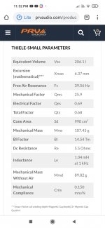
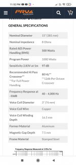
I will be using PRV 15W1000V2. (Ts parameters attached)
H frame size I prefer as compact as possible.
Something like 18" wide and 18" high, and front cavity depth 8" and rear cavity depth 8" ( if these dimensions are possible)
Crossover point anything that works between 80hz to 150hz with that h frame size.
Room size is small 11ft x 16ft.
Amp power is not a problem.
I will study and understand all the inputs you gave.
Thank you so much everyone for taking time and explaining.
Attachments
He wants the length to be shorter than c/4(100Hz). If "c" means 1125 fps, then the tunnel length should be shorter than 33.75". This keeps any tunnel 1/4 wave resonance far and away from your 100 Hz crossover frequency, while adding distance between the front and back wave of the driver. This distance is an improvement over simply putting the 15" driver on a reasonably wide baffle board, by rearranging the geometry form - without getting into trouble from resonant peaks.
I have the same crossover frequency, only I'm using 18" drivers. I've yet to construct my "U" tunnels, as I'm unsure if the baffle matching material I have on hand is enough, or if I want to use it for another set, or... I've got a couple large boards of this stuff stashed under my bed, so I'm "sleeping on it"!
By the word "tunnel length" do you mean the total depth of the H frame?? I mean, the front cavity depth + rear cavity depth.
The "r" stands for radius, hence it's "effective" because the cavity is rectangular. I'm not sure whether this calculator may be useful Cavity Resonance
thanks for sharing !!
I will be using PRV 15W1000V2.
H frame size I prefer as compact as possible.
Something like 18" wide and 18" high, and front cavity depth 8" and rear cavity depth 8"
Attachments


Thank you so much for the simulation.
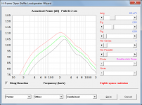
So for a 18" x18" h frame with 8" deep front cavity, and 8" deep rear cavity...
This graph shows there will be just a peak between 200hz and 300hz ???
So for a 18" x18" h frame with 8" deep front cavity, and 8" deep rear cavity...
This graph shows there will be just a peak between 200hz and 300hz ???
By the word "tunnel length" do you mean the total depth of the H frame?? I mean, the front cavity depth + rear cavity depth.
Yes. In my build, it would be a U because I'd rather not frame up the front of my existing board - and have plenty of space "back there".
Remember, the frame or tunnel is supposed to operate well below your crossover, so the sim is saying that peak is 2-3X higher than your cross at 100. Martin wanted 4X.
You can go a bit longer in the tunnel or lower in the cross, just stay away from the peak ;')
Some years ago, I built the MJK OB and H-Frame as designed using the Jordan full rangers and passive crossover. It's a great setup, BUT they like to be 3 to 5 feet from the walls. Not much WAF in the design. Hope this isn't too far off topic. Bill
This graph shows there will be just a peak between 200hz and 300hz ???
Correct, using the H-frame dimensions and driver parameter values you provided.
Some years ago, I built the MJK OB and H-Frame as designed using the Jordan full rangers and passive crossover. It's a great setup, BUT they like to be 3 to 5 feet from the walls. Not much WAF in the design. Hope this isn't too far off topic. Bill
You can put an H-frame against the side walls, it will give more output and in a small room make little to no difference to the sound.
I ordered the driver and il get it soon.
Il share the pics as soon as I build it.
Thanks a lot to each and everyone here for your valuable inputs guys. You people are awesome !!!
Il share the pics as soon as I build it.
Thanks a lot to each and everyone here for your valuable inputs guys. You people are awesome !!!
It may not be relevant but then again it may be too.
There's this modified Karlson design for an OB sub, the KaZBa.
Rockin' the KaZba Dipole (K aperture Z-baffle Dipole)
There's this modified Karlson design for an OB sub, the KaZBa.
Rockin' the KaZba Dipole (K aperture Z-baffle Dipole)
Correct, using the H-frame dimensions and driver parameter values you provided.
Big thanks to you David for developing Hornresp with sliders for H-frame OB dimension designing.
Can I ask how Hornresp models resonance in an H-frame? Are there two sources?
1. quarter wave of the depth?
2. half wave of the opening dimensions eg width?
Hi kazap,
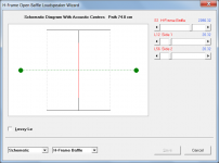
Hornresp analyses the H-frame open baffle system as a compound horn, with horn 1 and horn 2 being cylindrical segments having identical cross-sectional areas. The lengths of each segment can be different, if so desired. Resonances are automatically taken into account by the horn simulation model. The acoustical impedance loading each side of the diaphragm is determined, and the two acoustical power outputs are then calculated. For the purposes of combining the outputs, Hornresp calculates the positions of the two acoustic centres (shown in green in the attachment) using the method described by John Vanderkooy in AES Convention Papers 6912, 7102 and 7992.
Kind regards,
David
Attachments
You can put an H-frame against the side walls, it will give more output and in a small room make little to no difference to the sound.
Grey trace - located in centre of floor
Green trace - located on floor against wall
Red trace - located in corner
Attachments
Dear David its fantastic to see that graphs !!! Thanks a lot for making this thread more informative !! Im sure it helps a lot of people.
But there is always a peak.
How should I design a compact H frame or U frame to get a Flat frequency graph approximately 100hz to 40hz if that's possible. Assuming the room is 12x15ft and the driver is PRV15W1000V2 with Fs 40hz, Qts 0.68 and Xmax 6mm
But there is always a peak.
How should I design a compact H frame or U frame to get a Flat frequency graph approximately 100hz to 40hz if that's possible. Assuming the room is 12x15ft and the driver is PRV15W1000V2 with Fs 40hz, Qts 0.68 and Xmax 6mm
...But there is always a peak. ...
The way to read this chart is to examine only the vertical change at a given frequency (attention: scottjoplin).
At 40 Hz, the benefit of moving from worst to best is 13 dB. But at 600 Hz, it is like 6 dB.
So it does change the character of the sound based on the physics of air mass the driver faces and in a whole bunch of other ways too.
Which is why a separate sub makes sense in a lot of ways. A corner brings up the bass although other locations may have better all-around sound. Measure.
Can't say as I've thought anything is special about H dipole form. Isn't it purely a matter of maximizing path length any way you can and avoiding too much at any one path length? And grabbing hold of the driver resonance as a welcome booster.
Not right to apply the textbook physics of dipoles when waves are bouncing around wildly in rooms instead of neatly cancelling as per the textbook.
And for every frequency that meets its opposite at the edges, there's one that meets it duplication. How come nobody ever mentions that?
B.
Last edited:
- Home
- Loudspeakers
- Subwoofers
- Help to design H frame subwoofer