The free-air transfer function of the driver is quite different from what it will be in an enclosure, so the next step is to make enclosure(s) before testing further.
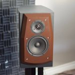
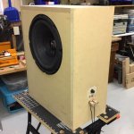
Project #3 was a two-way active system for a stereo pair. The first picture shows one of these loudspeakers. The MFB system is intended to be a low frequency extender for these. This means they will replace the speaker stands and shouldn't look too out-of-place standing beneath these speakers.
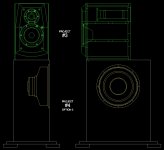
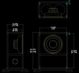
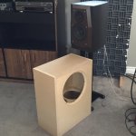
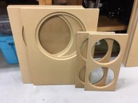
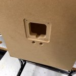
The second picture shows the concept for Project #4. I thought a front firing 12 inch driver would be too imposing and that a narrower front would look nicer so the driver is moved around to the side. For flexibility of positioning I'll make the pair symmetrical with a left and a right so the drivers for the pair can face toward or away from each other at floor level or just below the active system. I have started cutting wood (last picture).
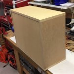
Nothing too fancy here with regard to the enclosures - just simple boxes with the internal volumes in accordance with the prior alignment calculations. I plan to house the MFB power supply and EVE boards in a separate small enclosure and the amplifier will be the vintage stereo amplifier that was used for the vented subs unless future testing finds it unsuitable (second last picture).
Project #3 is currently a vented design. This can become a closed box system with the addition of the LF extender bases.
Project #3 was a two-way active system for a stereo pair. The first picture shows one of these loudspeakers. The MFB system is intended to be a low frequency extender for these. This means they will replace the speaker stands and shouldn't look too out-of-place standing beneath these speakers.
The second picture shows the concept for Project #4. I thought a front firing 12 inch driver would be too imposing and that a narrower front would look nicer so the driver is moved around to the side. For flexibility of positioning I'll make the pair symmetrical with a left and a right so the drivers for the pair can face toward or away from each other at floor level or just below the active system. I have started cutting wood (last picture).
Nothing too fancy here with regard to the enclosures - just simple boxes with the internal volumes in accordance with the prior alignment calculations. I plan to house the MFB power supply and EVE boards in a separate small enclosure and the amplifier will be the vintage stereo amplifier that was used for the vented subs unless future testing finds it unsuitable (second last picture).
Project #3 is currently a vented design. This can become a closed box system with the addition of the LF extender bases.
Attachments
Last edited:
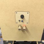
The first enclosure for testing is almost complete - only the connections remain to be done.
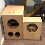
Note how much smaller the new enclosures are. Note that the MFB enclosures are about 1/4 the size of the vented enclosures.
The MFB enclosures will slide underneath the existing bookshelf speakers replacing the stands.
Note how much smaller the new enclosures are. Note that the MFB enclosures are about 1/4 the size of the vented enclosures.
The MFB enclosures will slide underneath the existing bookshelf speakers replacing the stands.
Attachments
Ah, testing. Or is that "ach, testing, oh no". What are the tests? How to A-B with listeners?
I thought your old abrupt start-and-stop tone bursts made sense and more sense than Linkwitz' EQ'd tone bursts. Very LF THD?
Percussion instruments, cow bells, maybe you could do you own live versus recorded test using your own sounds (like hitting a block of wood with a hammer).
I hope others will speak up here since I have never been satisfied to find good tests and never anything quantitative, which should be our goal.
B.
Ah, testing. Or is that "ach, testing, oh no". What are the tests? How to A-B with listeners?
I thought your old abrupt start-and-stop tone bursts made sense and more sense than Linkwitz' EQ'd tone bursts. Very LF THD?
Percussion instruments, cow bells, maybe you could do you own live versus recorded test using your own sounds (like hitting a block of wood with a hammer).
I hope others will speak up here since I have never been satisfied to find good tests and never anything quantitative, which should be our goal.
B.
The initial testing I have in mind might better be termed 'optimization'. A reasonable feedback factor needs to be achieved without instability. With this achieved, the performance benefits should follow. Part of this optimization may include tweaking the loop filtering to obtain a greater feedback factor in a range of interest - such as the region 2nd and 3rd order harmonics (40 - 120 Hz) for the lowest octave reproduced (20-40 Hz).
I'm open to suggestions on subsequent performance testing. REW will provide data related to the transfer function (phase, amplitude) and some distortion information. This should be telling and be fairly easy with a microphone.
The initial testing I have in mind might better be termed 'optimization'. ..
OK, but good to have testing strategy figured out early. Even stuff as simple as how to switch MFB on and off or how to do it silently or how to EQ the non-MFB status so FR matches the MFB FR (not valid comparing unless FRs match).
B.
Finishing the last 20% of the loudspeaker assembly to get ready to actually try it out takes the last 80% of the time. 🙂
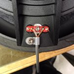
Note the added grounding for the accelerometer negative lead and the addition of a strain relief.
Note the added grounding for the accelerometer negative lead and the addition of a strain relief.
Attachments
Initial results:
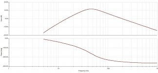
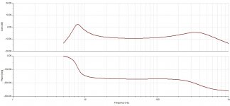
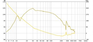
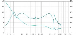
Here are the results of the very first attempt at adding feedback with the "proper" enclosure for the driver. The simulations in the first two charts come from Tina and the measurements in the last two charts come from REW as measured near field with a calibrated microphone.
I'm not sure whether to be happy or sad with these results. I'm also not sure what the next step should be.
The good news:
- MFB is working
- The practical amount of feedback has increased with the enclosure
- Circuit simulations largely seem to reflect actual performance which helps confirm simulation validity
The bad news:
- Frequency response is not as flat as expected. Circuit simulations largely seem to reflect actual performance which results in a transfer function that does not conform well the feedback Control (input) signal
- There is still a 60 Hz noise problem
- There is an unexplained notch at about 13 Hz and a nasty resonance at about 260 Hz
I thought the circuit simulations showing a dip in the frequency response in the middle of the feedback band were the result of some sort of error on my part, but apparently not so.
Attachments
What frequency(s) are you planning to cross it over at? High pass of 18Hz, Low Pass of 150Hz would seem appropriate. Mine is 22 and 125 for example...
What frequency(s) are you planning to cross it over at? High pass of 18Hz, Low Pass of 150Hz would seem appropriate. Mine is 22 and 125 for example...
In advance of actual testing, I was thinking of crossing over to the bookshelf speakers fairly low - say 80 - 100 Hz because they are quite capable to that point. In view of not wanting to excite the lower "MFB" resonance of the system I was also thinking of enabling high pass with the pole around 20 Hz to the EVE board. Right now it is disabled.
Plus and minus 3 dB from 15 to 140 Hz seems fabulous to me.
+1 Troystg
My impression is going north of maybe 150 Hz XO is out of reach for MFB (ditto for going super low). 150 Hz is pretty high for most people anyway* (and likewise trying to feed driver to play below maybe 18 Hz).
Love to see THD.
B.
* I cross over almost that high but not feasible to run ESL panels much lower without a mid-range cone speaker.
Plus and minus 3 dB from 15 to 140 Hz seems fabulous to me.
+1 Troystg
My impression is going north of maybe 150 Hz XO is out of reach for MFB (ditto for going super low). 150 Hz is pretty high for most people anyway* (and likewise trying to feed driver to play below maybe 18 Hz).
The middle dip looks simple to cure with EQ and anyway, everybody's bass needs to be shaped in the fine-tuning phase to get the right boost below maybe 45 Hz.
Love to see THD and tone bursts (as in earlier posts). Love to hear cricket-chirps with and without MFB.
B.
* I cross over almost that high but not feasible to run ESL panels much lower without a mid-range cone speaker.
Last edited:
Could it be the enclosure is not 100% airtight or driver mounting is leaking?
Definitely!!! I was thinking of this too and there are two known sources of leakage. One is the lack of a gasket right now on the speaker feedback terminal mounting plate. But this would be a minor leak.
The big leak is through the vented pole piece and this is going to act a bit like a tuned port. There is no dust cover on the speaker yet to seal this leak so I think we can be 99 and 44/100ths percent sure that this is the cause of the the 13 Hz anomaly. Below 13 Hz the speaker is going to start to think it is in free air too...
Last edited:
I forgot to mention something else that is quite important. There is currently no damping material in the cabinet. This won't change the LF alignment much, but there could be a higher frequency enclosure resonance that isn't damped right now.
Before further evaluation the dust cap should be glued back on and the damping material should be installed.
As you can see, this isn't ready for "prime-time testing" yet. This is still at the "oh cool, it is sort of working but..." stage. The nature of this beast is there are hurdles to get over before thorough performance testing gains enough "meaningfulness". This is why I haven't responded to your suggestions for test methods/data bentoronto. I will eventually endeavour to test this more rigorously though, I promise! 🙂
I'd have to sleep on it, but wouldn't you achieve the same result by sealing the far-end of the magnet? Or just adding stuffing to the hole? Or maybe not a good hypothesis for artifacts?
For testing, leaking can't matter too much if it's not excessive or undamped.
With a mere 12-inches, no sense pushing the driver too far low.
B.
For testing, leaking can't matter too much if it's not excessive or undamped.
With a mere 12-inches, no sense pushing the driver too far low.
B.
...wouldn't you achieve the same result by sealing the far-end of the magnet? Or just adding stuffing to the hole?...
The more I think about this, the more I think it is better to return the driver to its original design. Depending on the original objectives of the designers, VC cooling and/or velocity damping and/or cone flexural stiffness and/or something I haven't thought of could be adversely affected without the cap.
rscamp -> reed this paper page 19 fig 14.
http://rmsacoustics.nl/papers/whitepaperMFBtheory.pdf
Do you find answers to your resonance behaviour here?
Also the stiffness in the coupling between sensor and voice coil is important!!
http://rmsacoustics.nl/papers/whitepaperMFBtheory.pdf
Do you find answers to your resonance behaviour here?
Also the stiffness in the coupling between sensor and voice coil is important!!
I also recomend to read this paper. http://rmsacoustics.nl/papers/whitepaperMFBtheory.pdf
The high pass filter should be <= 16Hz and of order 6 or more.
The high pass filter should be <= 16Hz and of order 6 or more.
rscamp -> reed this paper page 19 fig 14.
http://rmsacoustics.nl/papers/whitepaperMFBtheory.pdf
Do you find answers to your resonance behaviour here?
I'm not a feedback stability expert, but my understanding is that to quantify these margins there really, really should be a test point on the EVE board to monitor the Feedback signal into the Adder. I mentioned this in Post #45.
Also the stiffness in the coupling between sensor and voice coil is important!!
I think this is about as stiff as it can be for the components used.
- Home
- Loudspeakers
- Subwoofers
- MFB for ACI SV12 Drivers using Piratelogic Electronics