After rereading this several times I'm almost 100 percent sure that what you have here is an offset driver layout....
Only in the sense that it's on the side of the filter chamber; acoustically, it's end loaded since the filter chamber has a slot port [S1] connecting it to the horn throat, just as his first pic, description implied. Since the chamber is acoustically so small, the driver can be mounted wherever it can fit, same as any small sealed, vented cab due to its air mass has a ~uniform particle density.
With a 2.5:1 CR though, I wonder how much power it can safely handle down around Fp.
Anyway, since he's made it plain he has all he needs to know from us, I'm going to sit back and see how much 'Penske's Unfair Advantage' he can tweak out of such a mature science where even an inventor as sharp as TD has bemoaned that he keeps bouncing off the 'wall of science' and the 'ancients keep stealing all my inventions'. 😉
Building the drivers required to advance horn performance is the stumbling block same as it's always been.
GM
LMAO... yeah its all in fun GM. 😀
I'll break no rules here and struggle to just get it right. If it weren't for you guys where do you think I'd be? Not having any fun thats for sure... you guys rock.
I'll break no rules here and struggle to just get it right. If it weren't for you guys where do you think I'd be? Not having any fun thats for sure... you guys rock.
Only in the sense that it's on the side of the filter chamber; acoustically, it's end loaded since the filter chamber has a slot port [S1] connecting it to the horn throat, just as his first pic, description implied. Since the chamber is acoustically so small, the driver can be mounted wherever it can fit, same as any small sealed, vented cab due to its air mass has a ~uniform particle density.
GM
If you want an accurate sim you have to sim it accurately. If it's not simulated as OD the sim won't show the huge notch that WILL show up in the measurement. If he keeps the driver as close as possible to the closed end the notch will end up far enough out of the pass band that it might not make any difference. And depending on how he enters the dimensions for Vtc and Atc (short and wide or long and narrow) this could affect the overall path length and the whole sim.
The problem I have is that people do terrible sloppy sims and then proclaim over and over and over that sims are not accurate. They build stuff that is completely different than what they simulated and then think it's the simulator's fault that the measurements don't match the sim.
This is a major source of frustration for me, and no matter how many incredibly accurate sims I produce to match existing measurements and explain what's going on this "simulation is a inaccurate tool" perception is hard and slow to break.
Don't even get me started on people that have never even tried to use a simulator or look at the high quality sims available everywhere that match measurements and STILL insist on telling the world that simulators are useless. These types are usually the loudest of the loudmouths.
Anyway, if it's not clear by now, accuracy in simulation is a really big deal for me. Even if the small details don't make any practical difference inside the passband the concepts are still important and things should be simulated accurately when possible.
With a 2.5:1 CR though, I wonder how much power it can safely handle down around Fp.
Probably doesn't matter since he said he's only going to feed it 200 watts or so. His solar panels are only capable of 4 or 500 watts output, so once the solar system and then the typically 60 - 90 percent efficient audio amps get done with converting the sunlight to speaker power (and I'm assuming the sub amp isn't the only thing drawing power) there really isn't a whole lot of power available. Having said that, I like to design for max performance potential too when possible and practical even if it's not going to be used that way immediately or even in the near future.
Last edited:
If I use my tweeters as an example, the 6.5 degree half angle exit of the driver matches the throat angle of an OS section with a FTA of say, 28 degrees, on to a hypex section with a FTA of say, 54 degrees then to a radius and on to a baffle. The intention is continuity with expansion to avoid termination reflections, and is probably more the domain of waveguiding, however as I see it..can you explain how you propose to use Hornresp's flare exit angle as part of the design process and why? And not in general terms, give an actual FTA number
..there is an element of the radiation space represented in the FTA which is relevant to this situation. I don't necessarily see this example as affecting the throat resistance, especially as that is part of the aim in this case.and explain how that (independent of the rest of the flare) applies to the radiation resistance of the environment.
If I use my tweeters as an example, the 6.5 degree half angle exit of the driver matches the throat angle of an OS section with a FTA of say, 28 degrees, on to a hypex section with a FTA of say, 54 degrees then to a radius and on to a baffle. The intention is continuity with expansion to avoid termination reflections, and is probably more the domain of waveguiding, however as I see it..
In this example the compression driver, the horn throat, the beginning of the second segment and the baffle are ALL physical parts. So like I said in the first place, assuming all of these pieces are round then the FTA can be useful info on matching these pieces together. I'm not sure how lathes or commercial manufacturing equipment are programmed but FTA might be useful info for telling them what to do. Or maybe not, I don't know.
The intent to expand continuously to avoid termination reflections however is a characteristic of the flare as a whole and this is can be simulated and designed without having any idea of what the FTA is for any of the pieces. Of course you can design each of these segments with AT being a design parameter if you want as David showed, but that alone does not avoid termination reflections. You still have the simulate the entire horn as a whole to find out how it is going to perform. And this can be done without knowing the angle of any of the pieces. So again, FTA is only one small part of the puzzle (that can be completely ignored if you like) even in this example, and even then only if all the parts are round.
When it comes to bass horns as we have been discussing, they don't have a compression driver with a specific exit angle (the cone itself has an angle but it doesn't need to match the throat angle so it hardly matters), (usually) none of the segments are round and the mouth/baffle interface doesn't usually have or need to be a smooth transition. And even if the bass horn was round you have both the segment data AND the Horn Data export chart to figure out the segment end sizes so FTA is not really even useful.
And not that this part matters since this is just an example, but you can't have a hyp/ex segment as a second segment in Hornresp. In fact if the first segment is OS you can't have a second segment at all, Hornresp won't allow it. If you want to include an extra radius at the mouth for a smooth baffle transition on an OS flare you can physically do that if you want but Hornresp won't let you simulate it so I'm not sure how FTA could even be useful information in that sense unless you were using it to program a lathe to make the piece.
..there is an element of the radiation space represented in the FTA which is relevant to this situation. I don't necessarily see this example as affecting the throat resistance, especially as that is part of the aim in this case.
I don't think there is, at least not without considering the flare as a whole. And since you can design the horn to provide the performance you want (including avoiding termination reflections) by specifying only segment type, length and cross sectional area at the ends without even knowing what angles are involved, I don't think FTA is really a primary design consideration.
I don't see FTA as useful for much except matching entrance/exit angles of physical round pieces together. I could be wrong but I don't think so and no one has mentioned anything to dispute that yet.
Filter chamber? In Hornresp its called the driver compression chamber I think... something like that.
Just to clarify, in a horn loudspeaker system the enclosed chamber behind the driver is more generally called the "rear compression chamber", or simply, the "compression chamber". In Hornresp the enclosed rear chamber is specified by parameters Vrc and Lrc. The rear chamber can be useful for reactance annulling. Although the throat chamber acts as an acoustical filter it is not usually specifically called a "filter chamber". In Hornresp, the throat chamber is specified by parameters Vtc and Atc.
When David says round he means round, in that the reported FTA ONLY applies to round horns. If you make it rectangular the FTA would be something completely different than what Hornresp reports.
Correct.
The rear chamber can be useful for reactance annulling.
If reactance annulling is characterized by obtaining the most possible output at the low knee and equalizing the pressures on both sides of the cone then it's not possible for true reactance annulling to happen until the horn gets very large, close to ideal full size for the low knee frequency.
I have seen reactance annulling referred to in reference to less than ideal full size front loaded horns and even in reference to tapped horns but I would challenge anyone to submit any type of horn design smaller than an ideal full size horn that provides max sensitivity at the low knee and equalizes pressure on both sides of the cone. As far as I know it can't be done so it's not possible to consider them reactance annulled.
Just a couple quick examples.
First we have the small 568 liter flh that I simulated early on in this thread (left) and a full size ideal reactance annulled horn on the right. (The "ideal" horn has a throat and rear chamber size that are too small to be practical but this is a stunning example of reactance annulled pressure cancellation so I chose to show it anyway.)
Looking at the full size horn the frequency response is flat down to the low knee so we know sensitivity at the low knee is fantastic. Second graph, efficiency is also outstanding at almost 70 percent at the low knee. Third graph, pressure on the front of the cone vs rear of the cone overlaid, shows almost perfect pressure cancellation of the pressure spike at the low knee. Fourth graph is total pressure, showing that huge pressure spike on both sides of the cone almost perfectly cancels.
Now looking at the small horn on the left, sensitivity at the low knee is low, efficiency is laughable at about 2 percent at the low knee, the pressures on either side of the cone are not the same (8300 pascals on the throat side and 4300 pascals on the rear chamber side at the low knee pressure peak) AND don't peak at exactly the same frequency. There's a bit of pressure cancellation as shown in the total pressure graph but not a whole lot because the pressure peaks are too different in amplitude and not peaking at the same frequency.
Second example - one of the tapped horns from this thread (left) vs a different full size flh (right).
The pressures on either side of the tapped horn cone (overlaid) are at such an incredibly different level that there is almost no cancellation of the pressure peak at the low knee. It's 5100 pascals on the front (throat) side, 500 pascals on the back (mouth) side for a combined total of 4700 pascals.
This full size flh is more "ideal" in that it's got a 2:1 compression ratio and the rear chamber is large enough to be practical. And it behaves much the same as the previous full size flh example. The low knee pressure peak is not at exactly the same amplitude or frequency on either side of the cone (this is a more average result than the previous full size flh that had an almost perfect match) but the total pressure graph shows the pressure cancellation of the low knee pressure peak is still remarkable.
I think these examples show pretty clearly that undersized horns don't have high sensitivity or efficiency at the low knee and there isn't much pressure cancellation at the low knee either. Full size ideal reactance annulled front loaded horns excel at all these things.
You can adjust the physical aspects of undersized horns so they do as well as they can in these categories but I don't think you could call them truly reactance annulled.
First we have the small 568 liter flh that I simulated early on in this thread (left) and a full size ideal reactance annulled horn on the right. (The "ideal" horn has a throat and rear chamber size that are too small to be practical but this is a stunning example of reactance annulled pressure cancellation so I chose to show it anyway.)
Looking at the full size horn the frequency response is flat down to the low knee so we know sensitivity at the low knee is fantastic. Second graph, efficiency is also outstanding at almost 70 percent at the low knee. Third graph, pressure on the front of the cone vs rear of the cone overlaid, shows almost perfect pressure cancellation of the pressure spike at the low knee. Fourth graph is total pressure, showing that huge pressure spike on both sides of the cone almost perfectly cancels.
Now looking at the small horn on the left, sensitivity at the low knee is low, efficiency is laughable at about 2 percent at the low knee, the pressures on either side of the cone are not the same (8300 pascals on the throat side and 4300 pascals on the rear chamber side at the low knee pressure peak) AND don't peak at exactly the same frequency. There's a bit of pressure cancellation as shown in the total pressure graph but not a whole lot because the pressure peaks are too different in amplitude and not peaking at the same frequency.
An externally hosted image should be here but it was not working when we last tested it.
Second example - one of the tapped horns from this thread (left) vs a different full size flh (right).
The pressures on either side of the tapped horn cone (overlaid) are at such an incredibly different level that there is almost no cancellation of the pressure peak at the low knee. It's 5100 pascals on the front (throat) side, 500 pascals on the back (mouth) side for a combined total of 4700 pascals.
This full size flh is more "ideal" in that it's got a 2:1 compression ratio and the rear chamber is large enough to be practical. And it behaves much the same as the previous full size flh example. The low knee pressure peak is not at exactly the same amplitude or frequency on either side of the cone (this is a more average result than the previous full size flh that had an almost perfect match) but the total pressure graph shows the pressure cancellation of the low knee pressure peak is still remarkable.
An externally hosted image should be here but it was not working when we last tested it.
I think these examples show pretty clearly that undersized horns don't have high sensitivity or efficiency at the low knee and there isn't much pressure cancellation at the low knee either. Full size ideal reactance annulled front loaded horns excel at all these things.
You can adjust the physical aspects of undersized horns so they do as well as they can in these categories but I don't think you could call them truly reactance annulled.
Last edited:
Whether or not you consider playing with the rear chamber volume in an undersized horn true reactance annulling or not (I don't, and I don't think tapped horns can be reactance annulled at all) I think some of these terms are misapplied when talking about undersized horns.
As an aside, another common catchphrase that I often hear is "horns match the impedance of the air to the cone", and they may go on to talk about efficiency. On the off chance that anyone cares at all (OP seems interested in "true" front loaded horns), here's a reply on that subject that I posted in another forum a few days ago.
This is the quote I was responding to - "The other thing it does is increase the air impedance to closer match the cone.
This causes the efficiency of the system to increase (more SPL for a given wattage) at nearly ALL frequencies (not just at box tuning.)
I think there are at least a few characteristics of full size ideal horns that are misapplied when discussing very small horns. A lot of things you read about true full size front loaded horns simply don't apply to much smaller front loaded horns or tapped horns. The impedance matching thing in particular doesn't seem to apply to small front loaded horns or tapped horns any more than it applies to transmission lines (which are very similar to small front loaded horns apart from the sealed rear chamber and remarkably similar to tapped horns), and nobody ever says this about transmission lines.
As an aside, another common catchphrase that I often hear is "horns match the impedance of the air to the cone", and they may go on to talk about efficiency. On the off chance that anyone cares at all (OP seems interested in "true" front loaded horns), here's a reply on that subject that I posted in another forum a few days ago.
This is the quote I was responding to - "The other thing it does is increase the air impedance to closer match the cone.
This causes the efficiency of the system to increase (more SPL for a given wattage) at nearly ALL frequencies (not just at box tuning.)
What you are saying has aspects of truth but it's pretty complicated and for the most part these horn attributes that you describe don't really apply to horns that are less than ideal full size for the low knee frequency.
To illustrate what's really going on let's examine a couple of different horns. They are both very large, but one is small compared to the low knee frequency and one is the ideal size (which means it's huge). Both these horns use the same driver but the horns are very different. The small one is still very large at almost 750 liters and with a mouth size of 6550 sq cm but it is still massively undersized compared to it's low knee frequency wavelength. The large one is ideally suited to it's low knee frequency, having a mouth size of over 50000 sq cm and a volume of almost 5000 liters.
An externally hosted image should be here but it was not working when we last tested it.
This is one of those old sayings that gets passed on all the time but it's not really true at all for small horns. Let's look at the impedance curve of the two example horns. Small on left, large on right.
An externally hosted image should be here but it was not working when we last tested it.
The small horn has an impedance curve that looks a lot like a transmission line. The large horn's impedance curve is much different. The spikes are damped, the dips are not as deep and the average level in the passband is higher.
In the small horn there are narrow bands of very high efficiency where the huge impedance spikes are and in between the spikes the efficiency is very low. The large horn has a higher level of efficiency across the entire passband due to it's sheer size and a much more calm impedance curve. This is what they mean by impedance matching and it doesn't apply to small horns. The impedance curve is where you see it but that's not really what they are talking about either. What they mean is that the impedance curve, the frequency response and everything else is smooth, not spiky so the cone is able to "see" a more constant radiation resistance in the air load at all frequencies in the passband.
Here's actual efficiency. Small horn on left, large on right, 120 liter ported box tuned to about 32 hz on bottom. The small horn does have a lot more efficiency than the much smaller ported box at most frequencies, that's to be expected based on size and having so many impedance peaks inside the passband. The large horn efficiency is much higher than both.
Clearly efficiency spikes at the same frequencies the impedance peaks are at. So if you line up a bunch of impedance peaks inside the passband you can have boosted efficiency for as much as a 3 octave passband. And the larger the enclosure, the more acoustic gain, the more efficiency.
An externally hosted image should be here but it was not working when we last tested it.
I think there are at least a few characteristics of full size ideal horns that are misapplied when discussing very small horns. A lot of things you read about true full size front loaded horns simply don't apply to much smaller front loaded horns or tapped horns. The impedance matching thing in particular doesn't seem to apply to small front loaded horns or tapped horns any more than it applies to transmission lines (which are very similar to small front loaded horns apart from the sealed rear chamber and remarkably similar to tapped horns), and nobody ever says this about transmission lines.
Last edited:
Fourth graph is total pressure,...
Oops, forgot to include the 4th graph and it's too late to edit the post. Here's the same image again but with the 4th (bottom) total pressure graphs included.
An externally hosted image should be here but it was not working when we last tested it.
If reactance annulling is characterized by obtaining the most possible output at the low knee and equalizing the pressures on both sides of the cone then it's not possible for true reactance annulling to happen until the horn gets very large, close to ideal full size for the low knee frequency.
I have seen reactance annulling referred to in reference to less than ideal full size front loaded horns and even in reference to tapped horns but I would challenge anyone to submit any type of horn design smaller than an ideal full size horn that provides max sensitivity at the low knee and equalizes pressure on both sides of the cone. As far as I know it can't be done so it's not possible to consider them reactance annulled.
Reactance annulling, as the term implies, simply uses rear chamber compliance reactance to 'cancel out' horn throat mass reactance. Paul Klipsch used this technique to good effect in the design of his classic corner bass horn, as documented in his seminal 1941 paper "A Low Frequency Horn of Small Dimensions".
To quote from the Klipsch paper:
"The air chamber behind the diaphragm is designed to offset the mass reactance of the throat impedance at low frequencies."
The attached article on reactance annulling may be of interest.
Attachments
I don't think tapped horns can be reactance annulled at all
Correct. The technique cannot be used with a tapped horn because there is no closed rear chamber behind the driver diaphragm.
small horn
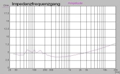
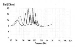
Hello you are right, so smaller the horn so bigger the comb filter effect,
but what happend if you combin two different horns, one with the dip in the peak of the other, connected parallel?
you get one oktave more bass and NO SPL rise ~150Hz, lowest and smooth membran movement, here an example
Kornett
Attachments
LMAO... yeah its all in fun GM. 😀
I'll break no rules here and struggle to just get it right. If it weren't for you guys where do you think I'd be? Not having any fun thats for sure... you guys rock.
Understood, I got interested in TL/horn theory early on due to wanting to replicate the big cinema horns life-like reproduction in a home version size using inexpensive drivers, but it turned into an obsession after seeing the Ford GT40's revolutionary 'bundle of snakes' exhaust system and get my own 'Penske's Unfair Advantage', which I did good enough to have SCCA's tech inspectors rule them illegal not because they broke any rules, but because they weren't 'in the spirit' of an amateur's racing league's rules.
Anyway, even without us, still a lot better than us old folks that didn't have T/S filter theory, computers, internet, etc, not to mention the folks who did know weren't for the most part willing to part with their hard won knowledge to the point were even as late as when I got on-line I was openly trashed both on-line and in expletive loaded PMs and/or censored and outright banned from a couple of early audio BBs for my totally erroneous, BS, self promoting, etc., 'agendas'.
One even sent me a virus laden-ed PM that completely trashed my computer to shut me up since it was before the days when folks had to worry about such things. It wasn't until Tom Danley joined the basslist that I found an on-line 'kindred spirit' and even he had a bit of a hard time convincing some of the more knowledgeable DIYers 'practiced in the art' of the horn theory set forth in patents, textbooks.
GM
Reactance annulling, as the term implies, simply uses rear chamber compliance reactance to 'cancel out' horn throat mass reactance. Paul Klipsch used this technique to good effect in the design of his classic corner bass horn, as documented in his seminal 1941 paper "A Low Frequency Horn of Small Dimensions".
To quote from the Klipsch paper:
"The air chamber behind the diaphragm is designed to offset the mass reactance of the throat impedance at low frequencies."
The attached article on reactance annulling may be of interest.
I read the linked paper very slowly and carefully a couple of times. I'm not sure I fully grasp all of it especially considering I'm mathematically challenged but I did come away with the following impressions. (I'm a bit out of my depth here so feel free to correct any mistakes.)
This paper seems to be concerned with full size ideal horns. It does mention "practical horns" in an offhand manner, saying they operate similarly but with reflections if the mouth is too small. But it doesn't define "practical" and doesn't mention if massively undersized horns are included in this category or if practical is referring to moderately undersized.
The first clue that massively undersized horns might not operate similarly is this equation.
wc (Md + Mh) - (Sd/wc) = 0
Assuming the same driver is used in two differently sized horns with the same passband, everything in that equation is a fixed value for both sizes except Mh.
wc = system angular resonant frequency, which is sq rt of wl x wh, which are in turn derived from fl and fh which are the desired passband bracket frequencies (I'm not even sure wc is an applicable parameter in a massively undersized horn without a painful detour through Leach's horn math paper to find the exact derivation of wc but let's assume it does apply to a massively undersized horn). Wc for OP's driver in a 18 - 100 hz passband is 266.
Md appears to be driver Mms (or maybe Mmd). Mmd for OP's driver is 147 grams.
Sd is driver Sd. OP's driver is 530 sq cm.
All of these are fixed values if the same driver and passband are used regardless of horn size.
Mh, mass of air in the horn, is the only value that is variable based on horn size.
So if we use previous examples from this thread, OP's driver was simulated in a 568 liter horn and a 22000+ liter horn, both with approximately the same passband. Air is approximately 1.19 grams per liter. That means that for these two differently sized horns, if you fill in the equation with these two different values for Mh you get a remarkably different formula.
This leads me to believe that if it's possible (and easy) to get this formula to sum to zero (or at least close to zero) with a full size horn, it might be incredibly difficult to get it to sum anywhere near zero with a massively undersized horn because Mh is different by literally orders of magnitude. I'm not sure how much rear chamber size can do about that.
Next, when looking at Figures 3 and 4, it's pretty clear that hyp/ex flares in the 0.5 - 0.7 T range are just about ideal for achieving a net zero reactance over a wide bandwidth aka reactance annulling.
I would guess that most massively undersized bass horns (including flh, tapped horn and tl) use a flare much closer to a purely conical flare with T = infinity or parabolic with T = ??? (whatever PAR T is, it's a lot higher than 0.7).
Since I don't know what the reactance of a conical or parabolic flare looks like I've used the T=5 flare (outlined in green on both Figure 3 and Figure 4 second copy - the green line looks almost straight when drawn on Figure 4 because the vertical scale is so squished).
Looking at the first copy of Figure 4, I've outlined the net reactance in red because it was pretty hard to see. Clearly the net reactance is very close to zero over a very wide bandwidth which is ideal.
Looking at the second copy of Figure 4 with the 0,7 flare T reactance erased and the flare T =5 reactance drawn on in green, it's clear to see that it won't sum to zero anywhere except at one frequency near where the speaker reactance and the horn reactance lines cross. This is less than ideal and I'm sure if I knew what the CON and PAR reactance looked like and had drawn them on the situation would look even worse, probably far worse.
An externally hosted image should be here but it was not working when we last tested it.
I'm not sure how much a rear chamber of ideal size can fix that less than ideal situation of very high flare T like a lot of bass horns with single expansion rate CON or PAR flares have.
And finally, I'm not sure how much of the story this last picture tells but it seems pretty telling. The acoustical impedance charts of a small horn vs a full size horn are very different. I assume the black line is resistance and the red line is reactance (since the red line crosses below zero and I'm pretty sure resistance can't be less than zero).
In the full size horn on the right the throat reactance and resistance spikes match remarkably well at the low knee, I assume this means reactance is annulled or cancelled.
In the small horn the throat resistance and reactance are not matching well, in fact they are headed in opposite directions for the most part. I assume this means reactance is not being cancelled out with any degree of success.
Now I'm not sure what this means in the big picture because changing the rear chamber size has no effect on the throat acoustical impedance (resistance and reactance) at all but I assume this is saying something about the topic.
An externally hosted image should be here but it was not working when we last tested it.
One last thing I got from this article - this statement -
"...reactance annulling ... cancel(s) out ... all or portions of the ... reactive elements ..."
leads me to believe that reactance annulling is not a matter of yes or no, it's a matter of how much. The fact that the word "portions" is used in that statement suggests (I think) that it's possible to do a very good job of reactance annulling (in a full size horn) and it's also possible to have a much lesser degree of reactance annulling in less than ideal situations, which could include undersized horns and inappropriate flare T, in which case it might not matter how ideal the rear chamber size is, it's not going to do a great job of cancelling the reactance. And I still suspect that in massively undersized horns you can't achieve a great degree of reactance cancellation no matter what you do.
Last edited:
Correct. The technique cannot be used with a tapped horn because there is no closed rear chamber behind the driver diaphragm.
WRT to this in particular the reactance annulling paper you linked seems to suggest that it is possible even without a rear chamber. In the last couple of paragraphs it actually talks about using a rear chamber vs using both sides of the cone to radiate, in which case they recommend experimenting with lacquer to stiffen up the driver.suspension. It doesn't specifically say anywhere that enclosure other than flh can be reactance annulled but it does seem to strongly suggest it in the last couple of paragraphs.
My point of contention is that I don't think any massively undersized design (front loaded or not) can have a high degree of reactance annulling. The front and back of the driver cone are seeing loads that are too different for the driver suspension or even an ideally sized rear chamber to do much about.
A fellow racer! Hearty handshake!
Yeah I been there too GM, and its still going on today and may forever. Studies show (with prexisting behavioural observation) that humans are resistant to change and new (or old, already been done) ideas or concepts require the self to adjust. It takes a bit of mental effort for the individual to accept and/or adapt to a slightly altered world view. Until the individual accepts though, the herd remains mired in accepted dogma, right or wrong. The result is as you stated... when facts cannot be understood or don't fit in, they are refuted and that reaction usually includes removal of the messenger who causes that discomfort.
Corporate trolls use elements of this known human psychology as tactical weapons in forums since its one of the best strategies they have to stop the individual from attaining new growth that inevitably leads to the herd growing. Corps can sell anything to a dumbed down populace, but cannot sell much to a wise man and enlightened populace. Until the individual becomes aware of his/her own natural psychological tendencies, change will continue to come slowly.

....
Anyway, even without us, still a lot better than us old folks that didn't have T/S filter theory, computers, internet, etc, not to mention the folks who did know weren't for the most part willing to part with their hard won knowledge to the point were even as late as when I got on-line I was openly trashed both on-line and in expletive loaded PMs and/or censored and outright banned from a couple of early audio BBs for my totally erroneous, BS, self promoting, etc., 'agendas'.
One even sent me a virus laden-ed PM that completely trashed my computer to shut me up since it was before the days when folks had to worry about such things. It wasn't until Tom Danley joined the basslist that I found an on-line 'kindred spirit' and even he had a bit of a hard time convincing some of the more knowledgeable DIYers 'practiced in the art' of the horn theory set forth in patents, textbooks.
GM
Yeah I been there too GM, and its still going on today and may forever. Studies show (with prexisting behavioural observation) that humans are resistant to change and new (or old, already been done) ideas or concepts require the self to adjust. It takes a bit of mental effort for the individual to accept and/or adapt to a slightly altered world view. Until the individual accepts though, the herd remains mired in accepted dogma, right or wrong. The result is as you stated... when facts cannot be understood or don't fit in, they are refuted and that reaction usually includes removal of the messenger who causes that discomfort.
Corporate trolls use elements of this known human psychology as tactical weapons in forums since its one of the best strategies they have to stop the individual from attaining new growth that inevitably leads to the herd growing. Corps can sell anything to a dumbed down populace, but cannot sell much to a wise man and enlightened populace. Until the individual becomes aware of his/her own natural psychological tendencies, change will continue to come slowly.
A fellow racer! Hearty handshake!
Studies show (with prexisting behavioural observation) that humans are resistant to change and new (or old, already been done) ideas or concepts require the self to adjust. It takes a bit of mental effort for the individual to accept and/or adapt to a slightly altered world view. Until the individual accepts though, the herd remains mired in accepted dogma, right or wrong. The result is as you stated... when facts cannot be understood or don't fit in, they are refuted and that reaction usually includes removal of the messenger who causes that discomfort.
a bit semmelweis reflex https://en.wikipedia.org/wiki/Semmelweis_reflex
- Status
- Not open for further replies.
- Home
- Loudspeakers
- Subwoofers
- FLH design basics for a dummy