
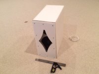
Dual W5-876SE XKi sub completed.
YOU ARE SO FAST!

")
Looks good ! , how does she sound?
Does 6th order bandpass also mean the slope of the bass falloff will be -6x6dB/octave or -36dB/octave?
From what i have seen it doesn't appear to be set in stone really , some of these "6th order" boxes have a smoother roll-off than others.
When the vent is behind the front baffle - any sound resulting from chuffing is really diminished and not as noticeable as a direct vent to the outside. The thing you have to deal with is turbulence which may cause port compression (meaning flow is less than you think). As long as you keep port velocity well under speed of sound by 1/10 the speed of sound or Mach 0.1, port compression should not be a problem. Mach 0.1 is 43m/s.
Chuffing is distortion whether it's partially hidden behind a barrier or not. Depending on vent size and shape 43 m/s might be a big problem.
Yep ! Thats right ....
I would also like to add that when the constriction is not at the end of the path (but rather mid-path) there is a much reduced likelihood of any kind of port compression and chuffing since according to theory the velocity is much reduced in the middle of the path (as opposed to the very end of the path) at FB ...
This strategy applies or can apply to most of the designs we have been discussing including the Karlflex , XKi , Karlsonator , this double Alpine box that XRK just presented to us etc and so on .................
In other words air particle velocity should not be as much of an issue just as long as we have designs that employ a significant length with increased area or expansion placed after the constricted portion of the path with the end of said section feeding the mouth/terminus/aperture ...
Akabak can show you velocity at any point inside the enclosure. This thread has been going on for months now, it's time to learn Akabak. High velocity is not the only issue, a few of the designs presented here can't be simulated in Hornresp, yet they are provided as complete plans for people to build. I'd be VERY wary of complex designs that have not been properly simulated. Building complex designs without measuring t/s parameters of the particular driver to be used is bad enough, building complex designs without properly simulating them is a whole other level of risk.
Yeah, when one studies up on flared vent design, the goal is either only a flare or two flares coupled together with no straight tube connecting them, so the pioneers viewed a baffle thickness vent as a very short tube with a rapidly expanding flare. It doesn't work this way of course, but WRT vent 'chuffing' it works well enough as long as it's CSA is at least 1/4Sd and < a ~1:1.273 aspect ratio, so chuffing isn't as issue with typically large K-slots. In theory, they shouldn't be >Sd for bass only apps.
GM
This is good guidance & background GM , thank you .... So when experimenting with different Apertures for bass only apps the exit's CSA can be between 1/4 to x1 the driver's SD, is that correct?
You're welcome! Correct, just depends on the front chamber volume/effective compression ratio the driver can safely handle at rated power.
GM
This is what happens when you use a modern high excursion driver with a vent size 1/4 of Sd. Vent is obviously round so aspect ratio is not an issue. Driver is readily available for purchase, measured by data-bass.com for t/s parameters, and verified to handle the amount of power this was simulated at (and more).
An externally hosted image should be here but it was not working when we last tested it.
I've said all this before in this thread and I'm not going to argue with you guys, but I'm saying this for the new guys that are following this thread and didn't see my earlier posts. There's absolutely no reason to use small restrictions in the line that cause high velocity. There's also no need for incredibly complex boxes with multiple chambers and/or flare rates / flare discontinuities. I haven't been following this thread but the one documented build of one of these plans that I did see months ago, the builder did notice "audible turbulence". IIRC those were the words he used. Large amounts of turbulence (including but not limited to chuffing and compression) in between sections inside the box are no different than large amounts of turbulence emanating from a ported box into a room - the result is distortion.
As I've said dozens of times in this forum there is no magic resonant enclosure type that produces more output for a given size. Size determines max output and shape determines where the impedance peaks are placed which determines frequency distribution of output. I showed this clearly (with pics) awhile ago in a different thread where I produced almost identical output to a reference design with four extremely different enclosure shapes, all five designs having almost exactly the same net internal volume. Post 75 to 79 in the following link.
http://www.diyaudio.com/forums/subw...bc-subs-reverse-engineered-8.html#post4102882
Last edited:
Oh come on now ... Thats no fun
Did Sabaspeed report any problems with chuffing in the 10S4 ML-Transflex? I don't recall that , i just remember him saying good things about how it performed ... Please show me the post# so i can see what you are talking about ..
Are you really going to troll us again? You are aware that it has been common practice for many years to have a throat chamber with a constriction with less than the driver's SD ... It works , and it works because a small throat chamber is at the pressure end of the path ... Check your theory man ..
People have been building boxes with constrictions at mid-path as well , is chuffing and distortion a major issue for the Karlsonator? That seems to a successful design if built properly so why do you suppose that is? ...
Besides we aren't using drivers with 20mm of one way excursion here, my most recent compact versions are made for low cost drivers to be used in multiples ...
Last edited:
YOU ARE SO FAST!
Looks good ! , how does she sound?
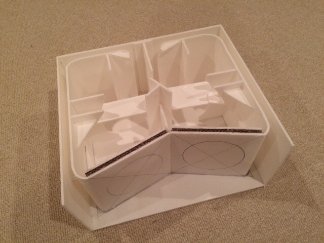
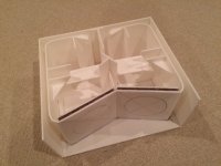
Thanks! I have not had a chance to listen to it other than maybe 2 songs as I had to run. I crossed it over at 200Hz (-48dB/oct LPF) in a FAST system with an XKi RS100-4 on top high passed at 200Hz (-24dB/oct HPF) and it sounded very nice. Deep articulate bass that surprised me. I put a lot of care in using rounded entrances for the vent and a rounded turn. Maybe that is helping the sound quality. I also used copious amounts of thin foam core bracing. The box is quite stiff for a 1 lb sub woofer enclosure that is 3/16in thick walls. Here is a detail of the internal channels and bracing.
@JAG: your admonitions regarding vent chuffing and compression are duly noted. Recall we had several posts back and forth regarding whether or not 30m/s flows in a vent automatically cause chuffing and harmonic distortion. I don't think it was clear cut. You have to look at Reynolds number, Mach number, and turbulence intensity from empirical data to see if it is a problem. I don't think 30m/s in a 1in wide channel vent was a problem.
Attachments
Last edited:
The code is right there for you to try. I posted a script for the XKi earlier and this one just required an extra driver and extra vent. So two more lines of code copied and pasted. Changed the TS params and set the volume and vent dimensions. That was it.
When the vent is behind the front baffle - any sound resulting from chuffing is really diminished and not as noticeable as a direct vent to the outside. The thing you have to deal with is turbulence which may cause port compression (meaning flow is less than you think). As long as you keep port velocity well under speed of sound by 1/10 the speed of sound or Mach 0.1, port compression should not be a problem. Mach 0.1 is 43m/s.
That mini XKi looks very cool!
I am currently on my work computer with no way of running AkAbak unfortunately, but what would happen to the response if I were to keep the vent sizes the same but instead make the front chamber 20L and the rear chamber 40L? this is just in an effort to get the cabinet to the same size as my current cab and the Karflex.
Would this raise Fb considerably?
Did Sabaspeed report any problems with chuffing in the 10S4 ML-Transflex? I don't recall that , i just remember him saying good things about how it performed ... Please show me the post# so i can see what you are talking about ..
Yes, he did. Not sure if that's the same design you are referring to, but here's what he said about the design from you that he built. "Ran some medium power 30 Hz tests (to find leaks, which are now sealed) and there was some notable "turbulence"." And note that that test was only at medium power.
Post 333. Link - http://www.diyaudio.com/forums/subw...ld-series-tuned-6th-order-34.html#post4032731
And by the way, you commented on the issue in post 339, and said the issue was overblown despite having a review that clearly said the design had audible turbulence.
Are you really going to troll us again? You are aware that it has been common practice for many years to have a throat chamber with a constriction with less than the driver's SD ... It works , and it works because a small throat chamber is at the pressure end of the path ... Check your theory man ..
People have been building boxes with constrictions at mid-path as well , is chuffing and distortion a major issue for the Karlsonator? That seems to a successful design if built properly so why do you suppose that is? ...
Besides we aren't using drivers with 20mm of one way excursion here, my most recent compact versions are made for low cost drivers to be used in multiples ...
I know the theory. Check your Akabak, man. I did, and showed the results. The results line up pretty well with Saba's review. I could talk about throat chamber duct sizes and Karlson designs but I'm not going to argue with you. As far as I know only one of your designs has actually been built and it had audible problems at medium power levels. Is it trolling if it's true? Is it trolling if I haven't made a single post in the last 1000 posts of this thread? Just a warning to the people who didn't see my first posts in this thread.
I like your creativity but drivers and wood cost a lot of money. Designs should be simulated properly before being presented to be built. If there's even a possibility of a problem you should build it yourself before advising others to build it, or at least provide a warning.
Last edited:
@JAG: your admonitions regarding vent chuffing and compression are duly noted. Recall we had several posts back and forth regarding whether or not 30m/s flows in a vent automatically cause chuffing and harmonic distortion. I don't think it was clear cut. You have to look at Reynolds number, Mach number, and turbulence intensity from empirical data to see if it is a problem. I don't think 30m/s in a 1in wide channel vent was a problem.
Compression and distortion testing at increasing power levels are the only way to know for sure.
FWIW, Flare It says a 1 inch diameter round port with no flare will see chuffing at 1 m/s at 20 hz, 2 m/s at 35 hz with no allowance for masking by content or seating position.

If we allow 55 percent masking that rises to 2 m/s at 20 hz and 3 m/s at 35 hz.
There could be a bunch of reasons that you didn't find it objectionable (especially if it was a foamcore enclosure) but I think distortion and compression testing would show a problem.
Compression and distortion testing at increasing power levels are the only way to know for sure.
FWIW, Flare It says a 1 inch diameter round port with no flare will see chuffing at 1 m/s at 20 hz, 2 m/s at 35 hz with no allowance for masking by content or seating position.
An externally hosted image should be here but it was not working when we last tested it.
If we allow 55 percent masking that rises to 2 m/s at 20 hz and 3 m/s at 35 hz.
There could be a bunch of reasons that you didn't find it objectionable (especially if it was a foamcore enclosure) but I think distortion and compression testing would show a problem.
We have been down this road before. Stop relying on black boxes that are wrong. Who is the author of Flare It? Obviously they have no clue of fluid mechanics. This is textbook begining Fluid Mechanics.
Again, Reynolds number below 2300 in pipe flow is purely laminar.
Re = U x D / nu where
U = velocity in m/s, D = diameter in m, nu = kinematic viscosity in m^2/sec
Re = 1 x 0.0254 / 20x10^-5 = 1270 or solidly laminar flow. If you have a sense of what 1m/s is, it is slow flow. 39 inches a second - no chuffing going on there.
Last edited:
Flare It was created using real world testing, measurements and listening tests. Within a reasonable range of sizes it isn't wrong.
One of the reasons why I said might not have been objectionable to you is that I doubt Flare It was tested with ports this small, and ports this small probably don't scale properly (as well as ports that are much larger than those tested).
Flare It isn't wrong within reasonable port sizes as tested.
I only posted this to show that really small ports are at a significant disadvantage. Test for yourself with measurements of distortion and compression and you will see this is true. Perhaps I should have shown a result from a larger port, one more in the range that was tested during the creation of the program.
FWIW I know nothing about your design but I'm sure the port was a lot larger than a 1 inch diameter circle, so the picture I posted has nothing to do with your design in particular.
Reynolds number will give you a decent idea of the port CORE velocity limit, but it is useless for predicting what will happen at the unflared port end where there is a massive impedance discontinuity, which is CHUFFING limit, not core limit. As you can see in the picture, Flare It says the CORE limit is 14 m/s, which probably isn't too far off from reality, but I agree, the chuffing limit is a bit incorrect.
As I said, distortion and compression testing are the only way to know for sure, but Flare It will get pretty close, within the range of port sizes it was tested for. Reynolds number alone is useless for predicting chuffing. Reynolds number is only applicable to air inside the duct (core limit), once it exits the duct it's a whole different ballgame (chuffing limit).
Last edited:
Not one of mine
Just-A-Guy ,
That was not my design, it was a dual driver Tapped Horn that he came up with for his Alpine 12s .... It didn't have any real constrictions to speak of as i recall, i think he did track down some of his noise issues, A main culprit ended up being a faulty driver with excess mechanical noise which he sent back for an exchange ..
I decided to buy benchtop tablesaw from Home Depot, just have to bolt it to this old desk on the porch, that should make it nice and stable ... I am ordering some Dayton drivers from PE to try out in a 60 liter Karlflex .... After the Karlflex for the Daytons i am planning on building a 25" tall Karflex for dual 10s (a friend wants it for his home theater) , as i get around to these builds i plan on posting pics and measurements ... Will be nice not having to inconvenience the guy down the road who had the woodshop i was using , or my neighbor (although my other neighbors might not like the sound the new tablesaw makes ) ...
As far as concerns and warnings about velocity: I have been mindful as of late, in fact i had to re-rate my 60L dual 10 Karflex recently because of air particle velocity limitations .... With this layout each cabinet scaling has it's own power level limitations based upon air-velocity estimations (if you even have enough xmax to get you there) ...
Im kind of excited to experiment with Karlson apertures , with their flare feature which should help to ease particle velocity a bit if used in series with the main path like the Karlsonator and XKi ...... For the drivers that need some amount of parallel loading i am growing more fond of the star shaped Aperture like XRK used recently ...
Yes, he did. Not sure if that's the same design you are referring to, but here's what he said about the design from you that he built. "Ran some medium power 30 Hz tests (to find leaks, which are now sealed) and there was some notable "turbulence"." And note that that test was only at medium power.
Post 333. Link - http://www.diyaudio.com/forums/subw...ld-series-tuned-6th-order-34.html#post4032731
And by the way, you commented on the issue in post 339, and said the issue was overblown despite having a review that clearly said the design had audible turbulence.
I like your creativity but drivers and wood cost a lot of money. Designs should be simulated properly before being presented to be built. If there's even a possibility of a problem you should build it yourself before advising others to build it, or at least provide a warning.
Just-A-Guy ,
That was not my design, it was a dual driver Tapped Horn that he came up with for his Alpine 12s .... It didn't have any real constrictions to speak of as i recall, i think he did track down some of his noise issues, A main culprit ended up being a faulty driver with excess mechanical noise which he sent back for an exchange ..
I decided to buy benchtop tablesaw from Home Depot, just have to bolt it to this old desk on the porch, that should make it nice and stable ... I am ordering some Dayton drivers from PE to try out in a 60 liter Karlflex .... After the Karlflex for the Daytons i am planning on building a 25" tall Karflex for dual 10s (a friend wants it for his home theater) ,
as i get around to these builds i plan on posting pics and measurements ... Will be nice not having to inconvenience the guy down the road who had the woodshop i was using , or my neighbor (although my other neighbors might not like the sound the new tablesaw makes ) ... As far as concerns and warnings about velocity: I have been mindful as of late, in fact i had to re-rate my 60L dual 10 Karflex recently because of air particle velocity limitations .... With this layout each cabinet scaling has it's own power level limitations based upon air-velocity estimations (if you even have enough xmax to get you there) ...
Im kind of excited to experiment with Karlson apertures , with their flare feature which should help to ease particle velocity a bit if used in series with the main path like the Karlsonator and XKi ...... For the drivers that need some amount of parallel loading i am growing more fond of the star shaped Aperture like XRK used recently ...
Last edited:
Hi X,
You did it again. Hyper fast work & amazing result. Why hasn't Bose given you a job?
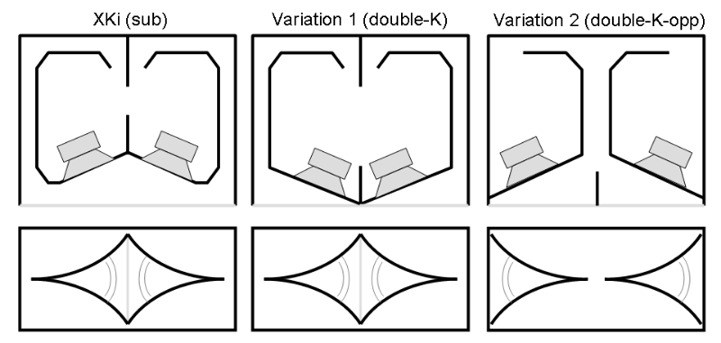
Looking at the diagram and your foamcore cab, I can't help thinking about the shape of original Karlsons. The orientation of the slant and the opening of the aperture are different from yours.
I mean, in a Karlson slot, it's deep at the slit and shallow at the wide opening. Is there a reason for it? Does it have better coupling between driver and port because the larger waveform of LF is forced its way out? I'm wondering.
So, here are some more combinations:
What do you think?
You did it again. Hyper fast work & amazing result. Why hasn't Bose given you a job?
Looking at the diagram and your foamcore cab, I can't help thinking about the shape of original Karlsons. The orientation of the slant and the opening of the aperture are different from yours.
I mean, in a Karlson slot, it's deep at the slit and shallow at the wide opening. Is there a reason for it? Does it have better coupling between driver and port because the larger waveform of LF is forced its way out? I'm wondering.
So, here are some more combinations:
What do you think?
Last edited:
Just-A-Guy ,
That was not my design, it was a dual driver Tapped Horn that he came up with for his Alpine 12s ....
Nice try, but this was WAY before he built the tapped horn.
On the same day as post 333 (where he mentioned the turbulence problem) he was still trying to figure out how to use Hornresp.
http://www.diyaudio.com/forums/subw...ld-series-tuned-6th-order-32.html#post4032508
Also from the same day, post 326 -
http://www.diyaudio.com/forums/subw...ld-series-tuned-6th-order-33.html#post4032666
He didn't even finish the matching second cab with the 10 inch driver design until the day after, the 22nd. He didn't even have his first Alpine 12 delivered at this point, that happened a couple of days later.
I was going to skim through and find out the date that the dual driver Alpine that he designed was finished and tested but by post 693 he was still only half done and I got bored.
http://www.diyaudio.com/forums/subw...ld-series-tuned-6th-order-70.html#post4051289
It was DEFINITELY your design with the turbulence problem that he was talking about.
I'm not happy that you just made me skim 50 pages of this thread but I knew my memory wasn't that bad.
Last edited:
Hi X,
You did it again. Hyper fast work & amazing result. Why hasn't Bose given you a job?
Looking at the diagram and your foamcore cab, I can't help thinking about the shape of original Karlsons. The orientation of the slant and the opening of the aperture are different from yours.
I mean, in a Karlson slot, it's deep at the slit and shallow at the wide opening. Is there a reason for it? Does it have better coupling between driver and port because the larger waveform of LF is forced its way out? I'm wondering.
So, here are some more combinations:
What do you think?
CLS,
You have some good questions here. I made the XKi sub the way it is because I wanted the drivers to focus their power at the exit aperture which is centrally located, and I wanted the sound from the feedback ducts to first pass by the drivers at a closer distance to effect the bandpass cone motion control to a greater extent. The simplified model that I have ignores all of these finer effects and one would need to use a 3d model like ABEC3 to capture the essence of the questions you ask. Although if I split the front chamber into multiple segments to capture the variation in angles and the splitter in the middle, it will probably produce a different result. I like both of your alternate proposed topologies and they would probably work. The last one is similar to the PPSL bandpass subs I have designed in the past with exception that you have a double aperture on the exit. Variation 1 would probably be best to get the highest amount if HF bandwidth out if you were operating it full range rather than a sub.
X
More info on XKi dual W5-876SE Subwoofer build here:
http://www.diyaudio.com/forums/full-range/268524-xki-xs-ab-initio-karlson-6th-order-bandpass-26.html#post4226956
http://www.diyaudio.com/forums/full-range/268524-xki-xs-ab-initio-karlson-6th-order-bandpass-26.html#post4226956
Stop relying on black boxes that are wrong. Who is the author of Flare It? Obviously they have no clue of fluid mechanics.
This line of questioning led me to reread the Flare It testing protocol that led to the creation of the program. If you want to question the validity of the program you need to read this page.
Port Flares - Evaluation of noise
The smallest port tested was 51 mm diameter (almost 4x more area than the picture I showed) and the largest was 152 mm diameter.
Results of 15 different port sizes and flare sizes from 0 to 75 mm were tested, measured and carefully listened to. (All ports and flares were round.)
Results from inputs outside of the range of sizes tested should be suspect. But within the range of tested port and flare sizes, Flare It is accurate. He does also mention that "Ports operating below about 10 m/sec generally have no problems with turbulence and compression. As velocity is increased beyond this, turbulence occurs as air exiting the port is forced to slow too quickly as it encounters the surrounding still air.", which should hold true for the smaller diameter ports too, regardless of the "chuffing line" results the program shows for small diameter ports. I probably should have noted that when I showed the example picture but I was trying to make a point (the same point that is made in the bolded sections below).
This is the summary of his testing. Bold added by me as those two points pertain to the point I was trying to make.
Summary of findings
Maximum usable velocity increases linearly with Area Ratio
There is a limiting velocity for any given diameter port, regardless of flare radius
Larger diameter ports have a higher usable velocity than smaller ports
Port performance varies with frequency
For moderate usage, the inside flare can be slightly smaller than the outside one
There's a bunch more info on that page too, and links to other pages that show the test boxes, flares and ports, and other stuff.
As a final note I will repeat that Reynolds number is absolutely and completely useless to predict chuffing. It's only useful to predict the core limit velocity inside the duct. As soon as the air exits the duct (which is where chuffing occurs) Reynolds number is useless.
Last edited:
I suppose the term "chuffing" refers to sudden expansion vortex generation from jet free expansion. I thought chuffing was referring to turbulent noise generated by a duct. In any case, Re number still is a principal parameter as "chuffing" is a phenomenon related to the relative ratio of momentum to viscous forces - the definition of Re number.
Anyone who says Re number is useless for characterization of "chuffing" doesn't understand fluid mechanics. Without viscous forces you have no vortex generation as it is result of viscous shear forces. That is, inviscid flows have no chuffing. The characterization of viscous flows is fundamentally linked to the Re number.
This is getting tiresome.
I will repeat that Reynolds number is absolutely and completely useless to predict chuffing
Anyone who says Re number is useless for characterization of "chuffing" doesn't understand fluid mechanics. Without viscous forces you have no vortex generation as it is result of viscous shear forces. That is, inviscid flows have no chuffing. The characterization of viscous flows is fundamentally linked to the Re number.
This is getting tiresome.
Last edited:
- Status
- This old topic is closed. If you want to reopen this topic, contact a moderator using the "Report Post" button.
- Home
- Loudspeakers
- Subwoofers
- New sub design? Constricted Transflex, simple build (series tuned 6th order)