Back to the Gunderson patent: I think there is an simple way to verify whether the additonal circuit really does the isolation and the improved performance. In fig 5, if you connect the base of Q24 to a few volts below the pos supply instead of to the output, the circuit changes to a current conveyer with an almost one current gain.
That would mean that the drive current from the Vas to the output stage doesn't change. However, because the emitter of the additional transistor now keeps the Vas output voltage fairly constant, the Ccb and other Vas capacitors are effectively isolated because they no longer see a varying voltage.
So, how would the circuit perform now?
Jan Didden
Hi, Janneman,
I just called Sandaan Hotel in Pangandaran. The line is connected, but there is no one answered. The phone is
62-265-639165 or 62-265-631230.
Then I called Pangandaran Tsunami Center
62-265-639234 or 62-265-630777
They said Sandaan Hotel is hit badly by the Tsunami. Pangandaran has 2 beaches, west and east. The tsunami hits the west beach, and unfortunately Sandaan Hotel is in this side of Pangandaran.
The tsunami is not as gigantic as the one in Aceh, but I don't know if the hotel will be back in operation when you arrived here or not.
Consider the impedance the VAS "sees". Again, refering to Fig. 5. It appears to me that with Q24 in place, the current the output transistors receive from the VAS stage is almost identical to that without Q24, at low frequencies (only differing by Q24s base current). This is Jan's observation.
BUT the voltage the VAS sees is different. Before, it was the voltage drop across the output devices, V3-V2, + Vout and now it is Q24 Vbe + Vout. Therefore the impedance the VAS stage sees is slightly different.
If we assume Q24 beta is so large as to be negligible, then is the question simply whether Q24 Vbe contributes less distortion to the main loop than the output stage Vbe?
Hi, Traderbam,
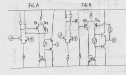
Your gunderson.jpg is nice. Q1+Q2 in your example is the expansion of Q24 in fig.5. Q1+Q2 is the "differential" version of this idea, while the original is the "singleton" version (like input of JLH amp). In your example, is that the original VAS transistor is driving the base of Q2? In Gunderson's, Q24 is common base, all current is coming from Q23. Maybe this is the difference with the "differential" version?
I think Q24 is doing more than just "adding" gain. For example, putting another transistor to form a differential VAS will be also adding gain. But here, Q24 also doing "comparing" between input and output. It is comparing between point 1 and point 2, and partially can do "fixing" if point 1 and point 2 is not balanced. Q24 shares the burden of "fixing" things, so the job of input differential pair (Q21-Q22) is helped so much by the action of Q24.
Q24 that can do "fixing" is helping the whole system much, compared if Q24 is only "adding" OL gain without able to do "fixing".
In Fig.A, Q1+Q2 is "adding" OL gain. But in Fig.B, Q1+Q2 is doing "fixing".
Attachments
I agree with David's analysis. The output current from Q24 is initially determined by the current from the Vas. Disregarding the Vbe, this is an almost 1:1 transport. However, the Vout also influences the output stage drive current. If, for instance, Vout falls, the Vbe increases and that causes more Q24 output current which works to get Vout up again, thereby countering the fall in Vout. Similar when Vout goes up. I don't know how much that gain is, as David rightly noted, it is also dependent on the load resistance (for AC) seen by the Vas. Anybody has an idea on that?
Jan Didden
Jan Didden
Yes. I put a differential here to show the similarity of the Gunderson circuit to an ordinary feedback loop.In your example, is that the original VAS transistor is driving the base of Q2?
Jan, I was considering the approximation that the output current from Q24 is always the VAS current. For if Q24 beta is very large and we neglect junction capacitances then Q24 Ic must equal Q24 Ie, always.The output current from Q24 is initially determined by the current from the Vas.
Any given change in output voltage will require the same current to the output stage regardless of whether Q24 is in circuit or not. The VAS has to supply the same current in either case. Therefore, the ONLY difference from the VAS point of view is the difference in Vbe between the output transistors in one case and Q24 in the other.
traderbam said:Yes. I put a differential here to show the similarity of the Gunderson circuit to an ordinary feedback loop.
Jan, I was considering the approximation that the output current from Q24 is always the VAS current. For if Q24 beta is very large and we neglect junction capacitances then Q24 Ic must equal Q24 Ie, always.
Any given change in output voltage will require the same current to the output stage regardless of whether Q24 is in circuit or not. The VAS has to supply the same current in either case. Therefore, the ONLY difference from the VAS point of view is the difference in Vbe between the output transistors in one case and Q24 in the other.
Yes, I see, I think you are right. So, what the varying Vbe does is just varying the Vas output voltage, iow the Vas output follows the Vout. Now, if that is true (and I think it is), it would mean that there is NO isolation! The Vas follows Vout is almost the same as the Vas follows the output stage input: in both cases there will be a signal on the Vas going through the capacitances and that was just what Gunderson wanted to avoid!
Jan Didden
I think the wording of the patent is a little confusing. He talks about isolating the output voltage from the VAS output but I think he reallty means he is trying to isolate the Vbe of the output stage from the VAS. The VAS will normally see Vbe + Vout. He is just trying to reduce the Vbe component. Of course we know that Vout will be full of distortion due to the non-linear current gain of the output stage no matter how much Vbe is linearised or reduced. So this is just a PARTIAL fix.
Even so, it is a clever idea. I wouldn't use it as prescribed because the current through Q24 needs to be quite a big proportion of the output stage bias current to make the improvement worthwhile and because it appears to demand undesirable stabilization measures. The cure may be worse than the disease!
Even so, it is a clever idea. I wouldn't use it as prescribed because the current through Q24 needs to be quite a big proportion of the output stage bias current to make the improvement worthwhile and because it appears to demand undesirable stabilization measures. The cure may be worse than the disease!
I think that the point of this circuit IS isolation.
The Ccm compensation capacitor has two purposes. It is a dominant pole to stabalise the amplifier, and at higher frequencies it gives local feedback around the VAS. Doug Self explains this in some detail, and more eliquantly than me. However, in a class B amp structure, in order to get a clean output, the signal at node 3 by necessity will have a large amount of distortion on it: Q25 output transistor turning on and off and R25 having half wave rectified currents flowing... So feeding the distorted node 3 into the VAS feedback loop will add these distortions to the signal path, rising at high frequencies. Now the THD plot on the patent makes sense.
As feedback is used (around VAS) EC could be a description, but without Q24 the EC is correcting node 3 (which needs to be distorted for the output to be clean). I think isolation covers the operation more clearly.
jagwap said:I think that the point of this circuit IS isolation.
The Ccm compensation capacitor has two purposes. It is a dominant pole to stabalise the amplifier, and at higher frequencies it gives local feedback around the VAS. Doug Self explains this in some detail, and more eliquantly than me. However, in a class B amp structure, in order to get a clean output, the signal at node 3 by necessity will have a large amount of distortion on it: Q25 output transistor turning on and off and R25 having half wave rectified currents flowing... So feeding the distorted node 3 into the VAS feedback loop will add these distortions to the signal path, rising at high frequencies. Now the THD plot on the patent makes sense.
As feedback is used (around VAS) EC could be a description, but without Q24 the EC is correcting node 3 (which needs to be distorted for the output to be clean). I think isolation covers the operation more clearly.
Hmm. I see what you are saying, but as you point out, the node driving the output stage MUST be a distorted signal. If indeed it is isolation, then it would mean that the Vas output stage is LESS distorted because its output is corrected by the local capacitive feedback.
So how would we then reconciliate a less distorted Vas output with the need to have a distorted drive signal for less output distortion?
Maybe part of the answer is that the Vas *voltage* is less distorted but the Vas delivered *current* is *more* distorted?
Jan Didden
janneman said:
Maybe part of the answer is that the Vas *voltage* is less distorted but the Vas delivered *current* is *more* distorted?
Jan Didden
Yes, but with more detail: while the output of the VAS needs to be distorted, the input to its feedback is clean.
jagwap said:
Yes, but with more detail: while the output of the VAS needs to be distorted, the input to its feedback is clean.
The output voltage of the Vas is undistorted if its input and feedback are undistorted voltages.
Current drive to the output stage can also be undistorted, the output stage input signal which needs to be undistorted will automagically be distorted even with an undistorted Vas output current because that output stage has a non-linear Zin!
I think I get it now.
Jan Didden
Exactly. when the VAS current is clean, the voltage is not, so isolating it will stop it being injected into the Ccm.
So the original question was what do we think? I think it certainly warrants investigation.
One reservation I have in using it in a power amp would be that the Ccm is now effectively wrapped around the output stage. The phase response of an output stage will vary in real world loads, and if this requires the domanant pole to be set so low to maintain stability as to undo the good it does then it is of limited value.
If Rotel use it then it can be made to work. They are a very commercially minded company making budget equipment. They don't tend put stuff in unless there's a reason. Especially if it's not immediately obvious to the customer.
Shows promise. Needs investigating...
It isn't "another feedback loop", but moving where the VAS takes its feedback from. Including the output stage looks good in principal, as long as stability isn't compromised. The Vbe linearity will be far greater than that of the output stage if that's what you mean, as the current through it is mostly constant. During clipping that will change drastically, and that may be where trouble starts.
This isn't another gain stage. It's just a level shifting follower. A cascode isn't a gain stage for the same reason.
Needs simulation, and preferably building.
This isn't another gain stage. It's just a level shifting follower. A cascode isn't a gain stage for the same reason.
Needs simulation, and preferably building.
Hi, Jagwap,
If it is about isolation, ordinary cascoded VAS would do isolation too? (like one in post #18). Why bother about modulating the base of Q24 following output stage, static cascode towards rail will do? Besides that, if Q23 is static cascoded toward +rail, the "Early Effect=modulated gm caused by modulated VCE) will be minimal.
The one that Rotel use is quite different. It uses voltage divider (output node-rail) as reference for Q24. It does not use zener.
Maybe zener is good in theory, but in real amp, if the supply voltage for the VAS is the same as for the output stage (front end not higher than output stage rails), zener in position of D20 will make the front end saturated badly when the output voltage approaching max rail voltage. Q23 will be full ON while Q24 will be OFF. The differential and VAS will be badly saturated this way. Maybe this is why Rotel does not use zener.
The one in Rotel amp may give distortion reduction, but it is because Q23 will suffer only half the "Early Effect" if Q24 is modulated half voltage like Rotel uses (47k-47k). The VCE swing of Q23 will be half compared when there is no Q24 attached.
"Fixing" effect is also disappear when using voltage divider as base input for Q24.
And, Q23 will only dissipate half heat compared when there is no Q24 used.
jagwap said:It isn't "another feedback loop", but moving where the VAS takes its feedback from. Including the output stage looks good in principal, as long as stability isn't compromised. The Vbe linearity will be far greater than that of the output stage if that's what you mean, as the current through it is mostly constant. During clipping that will change drastically, and that may be where trouble starts.
This isn't another gain stage. It's just a level shifting follower. A cascode isn't a gain stage for the same reason.
Needs simulation, and preferably building.
Agree. I initially also thought it's a gain stage with local fb, but there is no gain. Vas current in - same current out. It makes clever use of the high output Z of the Vas by modifying the Vas Vout (more linear) without touching the Vas Iout.
Clever, clever!
Jan Didden
lumanauw said:Hi, Jagwap,
If it is about isolation, ordinary cascoded VAS would do isolation too? (like one in post #18). Why bother about modulating the base of Q24 following output stage, static cascode towards rail will do? Besides that, if Q23 is static cascoded toward +rail, the "Early Effect=modulated gm caused by modulated VCE) will be minimal.
The one that Rotel use is quite different. It uses voltage divider (output node-rail) as reference for Q24. It does not use zener.
Maybe zener is good in theory, but in real amp, if the supply voltage for the VAS is the same as for the output stage (front end not higher than output stage rails), zener in position of D20 will make the front end saturated badly when the output voltage approaching max rail voltage. Q23 will be full ON while Q24 will be OFF. The differential and VAS will be badly saturated this way. Maybe this is why Rotel does not use zener.
The one in Rotel amp may give distortion reduction, but it is because Q23 will suffer only half the "Early Effect" if Q24 is modulated half voltage like Rotel uses (47k-47k). The VCE swing of Q23 will be half compared when there is no Q24 attached.
"Fixing" effect is also disappear when using voltage divider as base input for Q24.
And, Q23 will only dissipate half heat compared when there is no Q24 used.
An ordinary cascode would only isolate the the inherent parasitic miller Cobl, as Ccm would need to be put on the collector of the cascode in order to be the dominant pole for stability, and then still inject the voltage distortion of node 3.
The voltage divider in the Rotel (not seen it. Have a schematic?) will do the same as the zener version but with xdB less feedback (where x is the potential divider ratio, in this case 6dB). As you say, the early clipping of the zener solution is removed, but Q24 will still be hitting Q23 at clip.
I think a simulation will give more insight.
Disagree. There is a loop formed by Q24 and the output stage. Q24 emitter sees the output Z of the VAS, which decreases with f.It isn't "another feedback loop"
Only if the Q24 Ic is more "mostly constant" than that of the output stage. The Gm linearity of the output stage has the benefit over Q24 as there are two junctions in parallel and emitter degeneration resistors. Not so clear-cut.The Vbe linearity will be far greater than that of the output stage if that's what you mean, as the current through it is mostly constant.
Same thing in my book. At least, same in its implications for stability.This isn't another gain stage. It's just a level shifting follower.
So do it.I think a simulation will give more insight.

- Status
- This old topic is closed. If you want to reopen this topic, contact a moderator using the "Report Post" button.
- Home
- Amplifiers
- Solid State
- Gunderson compensation..