Tunnel of Love
I'm one step ahead of you T.") Be patient.
Be patient.
Cheers,
Shawn.
Originally posted by AndrewT
Hi Tom,
that tunnel leaks.
It will work much better if you can "tunnel" it.
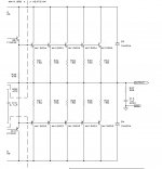
I note that the two sinks are spaced quite far apart and the fins on the outside are in passive air.
Can I suggest you make a sheet metal tunnel and bolt both sinks inside it but much closer together. A small gap between the outside fins and the tunnel inner wall will work quite well.
Remove the fan that is sucking and place the pushing fan at the bottom.
I'm one step ahead of you T.
Be patient. Might? Where is your faith? Please explain 5 pairs on twin drivers. Do you mean the drivers can not handle 5 pairs on the output?Now you might get 5pairs up and running (but how do 5pairs fit on twin drivers?).
Cheers,
Shawn.
Hi Tom,
the twin drivers expect to see the same number of output devices connected to each.
That forces you to adopt even numbers of output pairs.
2pr, 4pr, 6pr etc.
Or you could use the whole sink for just one channel and go 10pair. What a waste to leave some locations empty!
the twin drivers expect to see the same number of output devices connected to each.
That forces you to adopt even numbers of output pairs.
2pr, 4pr, 6pr etc.
Or you could use the whole sink for just one channel and go 10pair. What a waste to leave some locations empty!
1 Pair = 2
To me, a pair is a pair,1pair, 2 pair, 3 pair who cares? I don't get it? It is a push pull set up, as long as the NPN and PNP are in sets, then it's fine. The sink is set up for 2x10, that's 5 pairs for each channel. Are you saying the following will not work for each channel? The sink holds 20 pcs of TO-3, does that make better sense? If I'm speaking in tounges please say so but I thought I was straight forward?
Let me know if I need to get my head checked?
Cheers,
Shawn.
AndrewT said:Hi Tom,
the twin drivers expect to see the same number of output devices connected to each.
That forces you to adopt even numbers of output pairs.
2pr, 4pr, 6pr etc.
Or you could use the whole sink for just one channel and go 10pair. What a waste to leave some locations empty!
To me, a pair is a pair,1pair, 2 pair, 3 pair who cares? I don't get it? It is a push pull set up, as long as the NPN and PNP are in sets, then it's fine. The sink is set up for 2x10, that's 5 pairs for each channel. Are you saying the following will not work for each channel? The sink holds 20 pcs of TO-3, does that make better sense? If I'm speaking in tounges please say so but I thought I was straight forward?
Let me know if I need to get my head checked?
Cheers,
Shawn.
Attachments
Hi Tom,
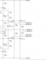
that extract from the schematic shows a 5pr fed from 1pair of drivers.
A KSA50 had 2pr fed from 1pr of drivers.
A KSA100 had exactly double that complement i.e. 1pr of drivers feeding 2pair of outputs and a second parallel pair of drivers feeding a second set of 2pr output devices.
So the twin drivers fed a 4pr output stage.
It follows that twin drivers MUST have an even number of pairs in the output stage if both drivers are connected to the same load.
You could run a 4pair stereo output and leave 4 empty locations, in the single tunnel. That would exactly duplicate the semiconductor complement fitted to the KSA100.
AndrewT said:Hi Tom,
that extract from the schematic shows a 5pr fed from 1pair of drivers.
A KSA50 had 2pr fed from 1pr of drivers.
A KSA100 had exactly double that complement i.e. 1pr of drivers feeding 2pair of outputs and a second parallel pair of drivers feeding a second set of 2pr output devices.
So the twin drivers fed a 4pr output stage.
It follows that twin drivers MUST have an even number of pairs in the output stage if both drivers are connected to the same load.
You could run a 4pair stereo output and leave 4 empty locations, in the single tunnel. That would exactly duplicate the semiconductor complement fitted to the KSA100.
Actually the image is from the KSA100 first version (my edit included) and now I'm looking at the MKII and you are correct! Dual drivers for the outputs!

Well, as I said earlier, there is a lot of space between the TO-3's and it would break my heart to leave spaces open so I'll just have to machine the rest in there. It should pose no problem as I currently see it. I will set it up for 6 pairs for each channel. This will give me the symmetry you pointed out.
I need to organize these documents in a more tidy fashion on my hard drive.
Onward and upward! Where are the boards for this amp?
Thanks Daddio!
Shawn.
Attachments
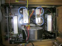
While you guys are looking at things I need to shoehorn a larger power supply into the KSA-100 chassis... Ths IS temporary!
I have a 2KVA plitron toroid that just fits in under the hood... 2 pair off 56K's and two bridges. Can I feed both bridges from the common AC secondary and use the common center tap for both channels or should I use one bridge and 2 caps per rail in this situation? Any other ideas that mnight work better would be appreciated?
PCB PRICING!
I got the board quote back late yesterday and it looks like we can do them for about $19.00 per board. The plan is to do 150 boards with gold plating, blue soldermask with white silk screen. I'm also having 50 made that are no soldermask or silkscreen with gold plated traces.These boards should be very flashy!
Everyone let me know if this sounds good and I'll post this and payment info on the WIKI and we can get it going. The total board cost is in excess of $3,000.00 and I can't front this much $$ but can make up the difference if needed so a good number of the payments are collected I will put the order through with a 4 week delivery schedule.
Board specs:
FR4
.093
2 Layers
6.378 x 5.510
2 oz Copper
Immersion Gold
SM - BLUE LPI
SS - White
Lets all argue this out till tommrrow and then I'll officially get the WIKI G.B. up and running.
Sorry... Have not had time yet to deal with the driver heat sink issue.....
Mark
Attachments
Mark A. Gulbrandsen said:While you guys are looking at things I need to shoehorn a larger power supply into the KSA-100 chassis... Ths IS temporary!
I have a 2KVA plitron toroid that just fits in under the hood... 2 pair off 56K's and two bridges. Can I feed both bridges from the common AC secondary and use the common center tap for both channels or should I use one bridge and 2 caps per rail in this situation? Any other ideas that mnight work better would be appreciated?
PCB PRICING!
I got the board quote back late yesterday and it looks like we can do them for about $19.00 per board. The plan is to do 150 boards with gold plating, blue soldermask with white silk screen. I'm also having 50 made that are no soldermask or silkscreen with gold plated traces.These boards should be very flashy!
Everyone let me know if this sounds good and I'll post this and payment info on the WIKI and we can get it going. The total board cost is in excess of $3,000.00 and I can't front this much $$ but can make up the difference if needed so a good number of the payments are collected I will put the order through with a 4 week delivery schedule.
Board specs:
FR4
.093
2 Layers
6.378 x 5.510
2 oz Copper
Immersion Gold
SM - BLUE LPI
SS - White
Lets all argue this out till tommrrow and then I'll officially get the WIKI G.B. up and running.
Sorry... Have not had time yet to deal with the driver heat sink issue.....
Mark
I'll go with one bridge+two caps/per channel
common ground from CT,what else?
Mark A. Gulbrandsen said:So its ok to feed two bridges from one secondary?????
Mark
why not?
ya teasing me?
you know-look at Graetz bridge-you feed two diodes in same time -from one secondary..........
why not two bridges............

off topic-mebbe I found you cheap source:
http://www.acsaudio.com/acs-redlight.htm
BobEllis said:Pass did it on the A75. I've got a pair running that way for 5 years.
uhh
if Papa does it
it's certainly wrong way


I built up a single regulator running at 65 V. I haven't built the negative regulator yet. I didn't have any issues with startup and it seemed quite stable at up to 300 mA (I cannot remember the AC input voltage but anything >68VDC input to the regs started nicely). AndrewT had startup problems at something around 40Vout. No guarantees, but it should work.
Changes are in the 65V BOM on my website, also a spreadsheet to calculate values and tell you when you need to go to MPSA42/92 (KSA rails will)
Of course the catch is I have no boards for sale. I will try to get a set running in one of my A75s by the end of the month. If all goes well and there is enough interest I could do another buy.
Hi Mark,
Power supplies from one trannie, eh? Everyone has their own bias or favorite way. Take a read of Dejan V. Veselinovic short description of different methods and their relative merits. Then you can make an informed decision about what is right for your situation.
http://www.zero-distortion.com/start.htm
under the heading "Designing your own power supply" on the main page.
HTH
Regards
Thats an interesting site which I will explore while I'm on the road sitting in the hotel room one night.
My reason for asking is because I just happen to have a large 2kva toroid laying around that with the primary conected for 240 volts will give me +/- 52 volts give or take a volt. I normally would use dual trannies or one with dual secondaries like I did in my KSA-50. This is only a proto for testing, etc as I also happened to have this case laying around...sinks are amslish but with a fan on each one it works fine. I may actually ou8tboard the whole supply instead of cramming it into this case..... Just need some smallish buss bar to run the DC rails to each channel!
Mark
Hi Mark,
Have you had time to experiment with the supply bypass caps on the PCB yet? For a small possible improvement the jumper that connects the front-end and driver supplies can be replaced with a 33ohm resistor or so to yield an RC filter for the front-end, or the two sets can be separately RC'ed from the main supply.
Have you had time to experiment with the supply bypass caps on the PCB yet? For a small possible improvement the jumper that connects the front-end and driver supplies can be replaced with a 33ohm resistor or so to yield an RC filter for the front-end, or the two sets can be separately RC'ed from the main supply.
BobEllis said:No guarantees, but it should work.
Say What !
I'm supposed to eat all those reg. boards of yours for breaky if they don't ?
Mark,
consider the other alternative.
Feeding both channels from one bridge would be equivalent to running a true 400 watt Class A Krell amp from a single bridge rectifier, at the least.
I suppose you've got huge bridge rectifiers ?
(3d: 4 bridges, no common ground)
Hi,
The two AC connections get paralleled to each rectifier. Then each rectifier feeds it's own channel. The outputs of the rectifiers are NOT paralleled.
The single centre tap goes straight to the audio ground where the 0Volt from both the capacitor pairs have also met up with the speaker returns etc..
yes.. Can I feed both bridges from the common AC secondary and use the common center tap for both channels
The two AC connections get paralleled to each rectifier. Then each rectifier feeds it's own channel. The outputs of the rectifiers are NOT paralleled.
The single centre tap goes straight to the audio ground where the 0Volt from both the capacitor pairs have also met up with the speaker returns etc..
- Home
- Amplifiers
- Solid State
- Krell KSA 100mkII Clone