Hi, PMA
Is it more audible in bass or midrange or treble?
Could you describe what sonic difference between one amp without error correction and the same amp with error correction (especially Hawksford type)?According to a large number of our listening tests there is an audible difference between the same stage with and without error correction
Is it more audible in bass or midrange or treble?
lumanauw said:
Could you describe what sonic difference between one amp without error correction and the same amp with error correction (especially Hawksford type)?
Is it more audible in bass or midrange or treble?
Well - I do not prefer speaking about midrange, treble etc. The biggest difference is in smoothness, liquidity of sound of the circuit with error correction. Also better in musical instruments resolution/definition.
ppl said:This must be in the Air I also have been recently playing with These ideas see attached
Looks like interesting circuit idea. Have you already tried it?
Hi, PMA,
Thanks for the explenation.
Non feedback power amp is usually notorious for the bass. It dont have control. Does matching non feedback amp with EC will be perfect?
Thanks for the explenation.
Non feedback power amp is usually notorious for the bass. It dont have control. Does matching non feedback amp with EC will be perfect?

PMA! about distortion? I have just simulated hawsford's error correction. It has a improvement at 20khz input signal, 38mV 2nd -> 1.6mV
PMA
Where do you get 2SK413/2SJ118 from?
I've searched for them but couldn't find.
Farnell says they are no longer manufactured.
How does the amp compare soniclly to your Class A 20W amp?
Does the amp need a lot of heatsink?
Are you running it from regulated supply?
I would like to try this design.
Bartek
PMA said:
Looks like interesting circuit idea. Have you already tried it?
Yes i have tested the circuit i posted. it sounded great however measured worse than the normal Class Ab biased version and was also unstable at low ICq. this was as installed in this DIY Headphone amp http://tangentsoft.net/audio/ppa/
driving assorted headphonens in the 32-300 Ohm range
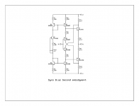
the IMD and THD were 10 times worse than the Class AB circuit. However sonicaly this version sounded better as PMA pointed out. si i began a second circuit that actualy started to behave like the Dynamicaly biased circuits i read about in the 100 or so patents on the subject. in essence you get the same THD at half the Class AB Icq. well since the previous version had more THD and way more IMD than Class AB and required three times the Current to be stable is not what i was reading these circuits are for so i came up with yet.
attached is this second idea
Attachments
thanh said:PMA! about distortion? I have just simulated hawsford's error correction. It has a improvement at 20khz input signal, 38mV 2nd -> 1.6mV
That fits. The distortion reduction is about 20dB - 40dB, depends on passive ciruit component values.
zygibajt said:PMA
Where do you get 2SK413/2SJ118 from?
I've searched for them but couldn't find.
Farnell says they are no longer manufactured.
Bartek
I simply have non-negligible amount of them on stock, I got them by accident. Yes, Hitachi do not manufacture them anymore.
zygibajt said:PMA
How does the amp compare soniclly to your Class A 20W amp?
Does the amp need a lot of heatsink?
Are you running it from regulated supply?
I would like to try this design.
Bartek
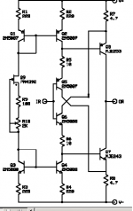
The new amp sonically resembles class A amps, but does not sound same. Sound of the circuit displayed also depends on opamp used. The conventional VFB opamps do not make good job, it was necessary to use fast CFB opamp - AD844. Please note the frequency compensation (680R, 56pF). For CFB opamps it is impossible to put capacitor from output to -input.
Heatsink requirements are much lower compared to the class A amp, because quiescent current is also much lower. The sound depends on quiescent current a bit. I would recommend quiescent current about 300mA.
PMA
Thanks a lot for the answers.
Are you planning posting the circuit recalculated for available fets (9540/540) any soon?
Sorry ,but don't have that much expirence to do it myself.
Bartek
Thanks a lot for the answers.
Are you planning posting the circuit recalculated for available fets (9540/540) any soon?
Sorry ,but don't have that much expirence to do it myself.
Bartek
Bartek,
send me an e-mail, I will recalculate it for you. Contrary to published circuit, it will be only simulated, not built. 413/118 version is built and can be seen on my web pages:
http://web.telecom.cz/macura/pm_ab1.html
send me an e-mail, I will recalculate it for you. Contrary to published circuit, it will be only simulated, not built. 413/118 version is built and can be seen on my web pages:
http://web.telecom.cz/macura/pm_ab1.html
PMA! and your circuit? I have no time to simulate your circuitPMA said:
That fits. The distortion reduction is about 20dB - 40dB, depends on passive ciruit component values.
😀
thanh said:
PMA! and your circuit? I have no time to simulate your circuit
😀
I spoke about my circuit.
- Home
- Amplifiers
- Solid State
- New error correction amp