") Given the high gain of the standard amp you will not need much in the way of gain for a preamp, more just a nice buffer/input selector.
Given the high gain of the standard amp you will not need much in the way of gain for a preamp, more just a nice buffer/input selector.I've been looking at 606's and 405s, actually. I've seen all the Kieth Snook's mods/upgrades for the 405, looks very interesting. I might look into that after I sort out the preamp.
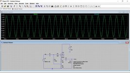
I got some advice on a line stage on another thread, and I'm going to go with a cathode follower design. I'm down to a choice between one from Glassware, a board from another user on here or possibly this Muchedumbre Buffer Preamp – wauwatosa tube factory.
I got some advice on a line stage on another thread, and I'm going to go with a cathode follower design. I'm down to a choice between one from Glassware, a board from another user on here or possibly this Muchedumbre Buffer Preamp – wauwatosa tube factory.
Ah, ok. I'll have a question about that in a min, but can I ask you something else quickly. I've just noticed that the 47pF polystyrene caps I put in at C8 are rated high enough for voltage. The manual says they should be 350V 1%, Silver Mica. The ones I've put in are only 160V, so I've taken these out and put in the old ones.
Why would the voltage rating be so high for these? There's nowhere near that much voltage anywhere in the circuit, so is it for something like to make sure that cap has low ESR? I've also just noticed that the caps put in at C2 by Dada Electronics are only rated 100V whereas they should be 250V. Is this anything to be concerned about?
Why would the voltage rating be so high for these? There's nowhere near that much voltage anywhere in the circuit, so is it for something like to make sure that cap has low ESR? I've also just noticed that the caps put in at C2 by Dada Electronics are only rated 100V whereas they should be 250V. Is this anything to be concerned about?
Last edited:
C8 sees across it essentially whatever is at the speaker output so it can only ever see one or other rail value at any given time (worst case) which is what, about 40 volts or so.
160v poly has to be fine. ESR doesn't really come into it with such tiny values, 47pF has a reactance of around 170,000 ohms at 20kHz, and much higher still at lower frequencies. 350 volt working was a common value back in the day for silver mica.
C2 sees almost no voltage across it. What Quad used was probably based on nothing more than cost and availability and using standard common commercial grade parts.

Maybe... high gain solid state amps would need care used with anything like that preamp to avoid PSU noise creeping into things.
Oh, would you mind explaining in a bit more depth about that particular problem, and how I might avoid it? Were you referring to any of those designs in particular? I was close to going with the Glassware ACF-2 or the wtfamps Muchedumbre, but I’ll hold off in case I’m going with the wrong thing. Are you saying that the power supply needs to be designed and implemented well to avoid these issues?
Well the Quad is intrinsically a high gain amp and so even a little unwanted noise at the input will be troublesome.
The big question is how quiet the valve preamp is. Valves using unregulated supplies and with AC fed heaters will not be the quietest around. You also have things like induced hum from the transformers.
That's why I say you need care. It may well be fine but it is an unknown with no hum and noise figures quoted that I can see. I was looking at the one in the link.
With the headphone amp (with standard wall wart PS) I am using as a preamp, it has a relatively loud hum with the volume at 0, which I'm guessing is 50Hz mains hum. So I think that you're correct in saying it's prone to hum.
The Glassware ACF-2 (ACF-2 Octal Aikido Cathode Follower Kit) says it contains two power supplies, a high-voltage bipolar with an RC filter per channel and a low-voltage PS with a regulator. The description (in link above) says that the design is such that power supply noise is greatly mitigated, what do you think about this design?
I've have sent the owner a few messages with questions over the last few weeks, but unfortunately, I've had no reply
Here's also the manual, but for the 9-pin version: https://www.tubecad.com/2012/02/07/ACF-2 9-Pin.pdf
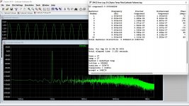
Identifying the frequency of hum can be a good clue to where it comes from. A pure deep tone is likely 50Hz and can be either a true ground loop (via mains leads and so on) or induced hum from proximity of transformers to circuitry and cables.
If it is more of a buzz then it is probably 100Hz which is power supply related. The ripple component on a DC line is 100Hz for a full wave bridge rectifier fed from 50Hz.
It is impossible to say with certainty how hum free all these will be. DC heaters eliminates that aspect but ultimately what is missing is a spec quoting actual hum and noise from the unit.
I compared the hum to both a 50Hz sine tone and a 100Hz, and I'm struggling to match it. It sounds like it's between the two to me. It's purely a clean hum and no buzz.
Can I use either my oscilloscope or the frequency setting on my multimeter to determine the frequency of the hum? I've had a google on how to do it, but can't find any specifics. I'm going to have a fiddle now, and see if I can do anything.
Can I use either my oscilloscope or the frequency setting on my multimeter to determine the frequency of the hum? I've had a google on how to do it, but can't find any specifics. I'm going to have a fiddle now, and see if I can do anything.
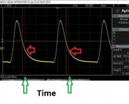
A scope is easiest. Just look for the repetition rate by picking any point on the waveform and looking for the next similar point. Count the time between them and calculate the frequency.
F=1/T
So at random... pick any two similar points and count the squares between them. Look at the scope timebase (say 5ms/div) and see how long one cycle lasts. Here it is four squares and so if the timebase were 5ms/div we have 20ms for one cycle.
F=1/20E-3 or 1/0.020 if you prefer which is 50 Hz
Make sure any variable scope settings are in the 'Cal' position.
Attachments
Thanks! I'm going to give this a go at the weekend. I've been a bit busy so I haven't got round to it, just started back at uni this week. I've also just noticed a buzzing in one channel of the new 306 (not the one I originally had the issue with), but a similar issue. I have swapped over some parts between the two, so I'll start with checking those first.
- Home
- Amplifiers
- Solid State
- Quad 306 buzz in right channel