Jan, if I understood correctly, you (as well as the majority) do not know anything,
Well, if you don't understand that an input signal, that starts from zero to some value in zero time, has an infinite bandwidth and an infinite number of harmonics, I can't help you.
Nobody can.
Maybe I just should bow to your superior intellect, then.

Jan
Last edited:
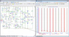
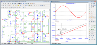
Let's simulate the spectrum of an ordinary first-order low-pass filter chain with a cutoff frequency of 160 kHz (for example) and a frequency of 1.6 MHz. See the difference on the charts through transient analysis, as you did above. It can be seen that this has nothing to do with the nonlinearity of the amplifier and characterizes it only as a low-pass filter. By disabling the input filter, you cannot exclude the bandwidth of the amplifier itself, which pushes you to try to make it more broadband.accidentally took the wrong model


So it looks like a sine

And this tail falls into the time window of the Fourier analysis.
Last edited:
Jan:
«Maybe I just should bow to your superior intellect, then.»
Jan, better bow your head to the developers of the MicroCap simulator
I have already explained to you several times that the program, when calculating the spectrum, uses one single period and adds the n-th number of the same periods in front and behind so that the signal becomes stationary. But your intellect is not enough to understand this.
In programs of version higher than 9, the minimum number of periods is limited to 4. If we use only 4 periods to calculate THD, then the program feeds only 4 periods to the amplifier and from the output it takes one single 4th period for analysis. In automatic mode, the program itself tests until the transients are over and the level of distortion is stabilized. We get what Audioprecision usually shows.
In good amplifiers, this process occurs instantly, since a minimum number of signal periods is sufficient. In bad amplifiers, this process takes a long time, but a low level of distortion, say, at the 100th period is a deception for the developer, but the ears cannot be fooled.
Jan, judging by your ideas, in order to make a blood test in a person, he needs to pump out all the blood, analyze and then pump it back into the body.
Graham Maynard (author of FCD) has repeatedly drawn attention to the negative impact of the choke at the amplifier output on sound quality.
John Curl also believes that amplifiers to amplify an audio signal should work stably without an additional choke, he argues that there is more harm than good from a choke and tries to develop amplifiers without a choke.
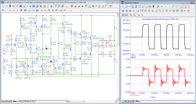
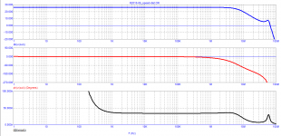
Here are the results of testing the amplifier with choke:
The output impedance stabilizes only in the 3rd period. This is how the amplifier will respond to the loudspeaker back EMF.
The amplifier is too tough for the effective load in the form of 0.5 and 2 μF.
John Curl also believes that amplifiers to amplify an audio signal should work stably without an additional choke, he argues that there is more harm than good from a choke and tries to develop amplifiers without a choke.
Here are the results of testing the amplifier with choke:
The output impedance stabilizes only in the 3rd period. This is how the amplifier will respond to the loudspeaker back EMF.
The amplifier is too tough for the effective load in the form of 0.5 and 2 μF.
Attachments
You don't know, because you don't know what comes next. Does the signal continue in the same manner? Is it a burst? The essence of the FFT in the sim is that it assumes the signal is periodic, as if the signal continues in the same way as it is shown.
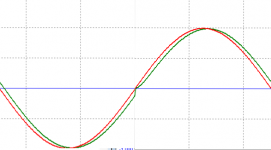
In your case, it appears that the beginning and the ending of the signal is at exactly the same phase point, so for the FFT this connects exactly and there are no discontinuities, and no harmonics created other than by the signal itself.
The graph shown by peufeu before illustrates it beautifully. It should be clear that by assuming the periodicity of the signal you use as input, you create discontinuities in the signal when the FFT assumes it is periodic, and this creates a whole slew of harmonics.
Jan
Last edited:
It should be clear that by assuming the periodicity of the signal you use as input, you create discontinuities in the signal when the FFT assumes it is periodic, and this creates a whole slew of harmonics.
Yes, he is using FFT on a signal that looks periodic but is not, because the discontinuity is hidden by the way the signal wraps around the display. If you put it in the center it becomes visually obvious. This is an incorrect way to use FFT, it does not work.
This is an incorrect way to use FFT, it does not work.
exactly right
OK, but is this test signal periodic?
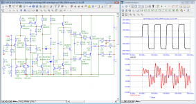
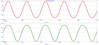
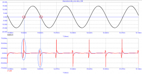
This is how the MicroCap simulator sees the signal of the first period at the output of the amplifier, adding to it the required number of periods in front and behind, so that the signal becomes periodic.
This is how the MicroCap simulator sees the signal of the first period at the output of the amplifier, adding to it the required number of periods in front and behind, so that the signal becomes periodic.
Attachments
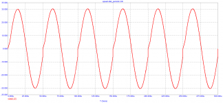
Jan, if I understand correctly, then the output voltage surges up and down when the signal crosses zero do not bother you and you normally treat it as periodic.
So that there are no surges in the signal of the first period (as MicroKap sees it), then make amplifiers according to the recommendations of Cyrill Hammer with a signal propagation delay time in the entire audio range and far beyond it, only a few ns
Consider that MicroCap sees the first period of the signal with crossover distortion at one zero crossing of the signal. That's all. The level of this crossover distortion depends only on the tPD.
Attachments
Last edited:
This is how the MicroCap simulator sees the signal of the first period at the output of the amplifier, adding to it the required number of periods in front and behind, so that the signal becomes periodic.
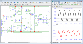
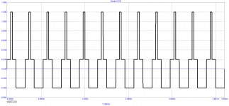
Yes, and the "thd" you are measuring is due to the step at the end of the period which is an effect of this splicing, it does not exist in reality.
In an ideal rectangular signal, the rise time of the edges is zero, only there these edges are for the entire signal amplitude from peak to peak (tens of volts).
In this case, MicroCap splices in exactly the same way, only the amplitude of the front at the splice in one of the zero crossings is from ten mV, up to several Volts - it depends on the signal propagation delay time (tPD). That's all.
Is it hard to understand?
In this case, MicroCap splices in exactly the same way, only the amplitude of the front at the splice in one of the zero crossings is from ten mV, up to several Volts - it depends on the signal propagation delay time (tPD). That's all.
Is it hard to understand?
Jan, if I understand correctly, then the output voltage surges up and down when the signal crosses zero do not bother you and you normally treat it as periodic.
So that there are no surges in the signal of the first period (as MicroKap sees it), then make amplifiers according to the recommendations of Cyrill Hammer with a signal propagation delay time in the entire audio range and far beyond it, only a few ns
Consider that MicroCap sees the first period of the signal with crossover distortion at one zero crossing of the signal. That's all. The level of this crossover distortion depends only on the tPD.
So now we are discussing cross-over distortion? It is not very honest to change the subject every time you are asked a serious question. It is very childish actually, and you never learn anything doing it. How old are you?
But yes, of course cross-over distortion does bother me. I want to minimize it in an amplifier.
How you can think it does not bother me I don't know, did you pull that out of your hat ;-) ?
Jan
Last edited:
Jan, I don’t understand who you mean. Or you just enjoy flooding.
Crossover distortion and velocity distortion are completely different types of distortion.
Crossover distortion occurs whenever the signal crosses zero.
Velocity distortions occur both when the frequency changes and when the signal amplitude changes.
I have pointed this out many times. As for the distortions of the first period (what Graham Maynard was looking at)? then they arise at the very beginning of the period and depend on both the magnitude of the group delay and its behavior both in the audio frequency band and behind the band.
I just gave an analogy between different types of distortions to make it clearer how MicroCap sees them.
What I mean is that it is impossible to discuss with you. One time you talk about FCD and FFT, then I or someone else comment on that, then you switch to discussing xover distortion.
Why not engage in a normal discussion?? This way you get nowhere, after all these months, you just repeat yourself and refuse to discuss.
The last few posts from peufeu and me try to engage you into a discussion of FFT. Maybe we are wrong, maybe you are wrong, that is not important, important is WHAT is wrong or correct. That is how we learn.
But you run away and start to discuss something else, in this case xover distortion.
Jan
Last edited:
- Home
- Amplifiers
- Solid State
- Musings on amp design... a thread split