I've been promising a follow-on for my 50W and 100W lateral MOSFET amplifiers for the longest time, but truth be told, without a valid use-case I simply can't get the energy up to design one. I could go for vanishingly low distortion, but I can't hear that. I could see how many power devices I could bung in parallel and brag about who's got the biggest, ahem, amp, while needlessly heating my house up. But no, none of that is terribly exciting.
I've been favouring my old Infinity speakers of late, mainly because my Ariels with the active 2-way 50W+50W lateral amplifier setup is in the living room, and I spend a lot of time in my study, listening to my Cyndi Lauper LPs and working. My big old Infinity RS-5b's are in there, and they sound pretty cool. So I've been thinking about how it'd be nice to roll a modern version; 10" or 12" woofer, dual mids, and a nice tweeter. An amp to drive such a setup might do 200W into the woofer, and 50W each into the mids and tweeter.
I like my lateral MOSFET amps, but I dislike excessive quiescent power consumption. I'm enamoured with my lovely old NAD 3240PE amps (I've gotten a couple working, and they're a nice amp). So what if we combine the two. A Lateral MOSFET version of the 3240. Aim to improve on the distortion specs by, say, 20dB. And don't waste current to get there. I've got some ideas on how to speed up the AEM6000 topology, so use that and wrap a NAD inspired class-H rail switcher around it.
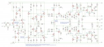
I've attached my circuit. It uses 2 pairs of Exicon 10N20/10P20 devices for the main amplifier, and is approximately based on the AEM6000. I've added a folded cascode to the front end, with a current mirror load. That improves the AEM6000 design by enough to mask the badness that the class-H rail switchers do.
The rail switchers are based on the 3240PE, but I've used a diffamp on the input. The whole mess is able to switch cleanly to envelope a 20KHz sine-wave without clobbering it, but when it starts turning on and off it imparts about a 20dB penalty to THD.
Power budget wise, I run the input diffamp at ~800µA per side, then ~2.5mA per side for the second stage, and ~6mA for the VAS (which is not differential). I've biased the MOSFETs at a paltry 20mA per device. This keeps the overall power budget to around 7W (compared to 13W for my 100W amp), which I think is an improvement.
THD is in the single-digit ppm figures up to 50W, after which the rail switches do their thing and the THD rises to about 0.003% at 1KHz. Still quite a lot better than the NAD. I'm confident it'll reliably do 200W into 8Ω, as the rail switches really do help to limit dissipation in the output drivers. I've set the supplies up to +/-35 and +/-70 V, so I could use a pair of 25VAC dual secondary toroidals, and run the other amps off the +/-35V rail. Input is my standard SST-404 JFET, so I expect something like 8ish nV/√Hz input referred noise.
I've set the gain for 20dB (X10). It's really very stable, so the gain can be pushed pretty-much as low as I like to improve the distortion figures. I can run a pre-driver as part of the active filter network to increase the gain with no distortion penalty.
I played around a lot with the compensation for the rail switches - there's a maddening compromise there between fast switching to keep up with transients (so it doesn't mangle square waves), and not pushing heaps of current into the output quicker than the servo system can compensate for.
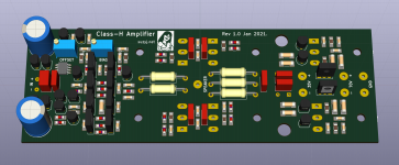
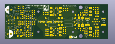
Now I'm up to laying out the PCB. I've eschewed SOT-23 transistors in favour of TO-92s, and grown the pads on my MELF and 1206 footprints a little to make it more soldering iron friendly. The PCB is currently at 160mm x 55mm with placement pretty-much sorted, but will likely change a tad while I do the routing.
As with everything I do now, schematic and layout are done in KiCAD, so it's easy for others to play with once I've finished.
Please see https://drive.google.com/drive/folders/1Ies9zDP7GDvZwC5QbxmRw1H3eZTN8h8A?usp=sharing for the kicad design files and gerbers. Use at your own risk. No warranty. All the usual **** covering caveats.
I've been favouring my old Infinity speakers of late, mainly because my Ariels with the active 2-way 50W+50W lateral amplifier setup is in the living room, and I spend a lot of time in my study, listening to my Cyndi Lauper LPs and working. My big old Infinity RS-5b's are in there, and they sound pretty cool. So I've been thinking about how it'd be nice to roll a modern version; 10" or 12" woofer, dual mids, and a nice tweeter. An amp to drive such a setup might do 200W into the woofer, and 50W each into the mids and tweeter.
I like my lateral MOSFET amps, but I dislike excessive quiescent power consumption. I'm enamoured with my lovely old NAD 3240PE amps (I've gotten a couple working, and they're a nice amp). So what if we combine the two. A Lateral MOSFET version of the 3240. Aim to improve on the distortion specs by, say, 20dB. And don't waste current to get there. I've got some ideas on how to speed up the AEM6000 topology, so use that and wrap a NAD inspired class-H rail switcher around it.
I've attached my circuit. It uses 2 pairs of Exicon 10N20/10P20 devices for the main amplifier, and is approximately based on the AEM6000. I've added a folded cascode to the front end, with a current mirror load. That improves the AEM6000 design by enough to mask the badness that the class-H rail switchers do.
The rail switchers are based on the 3240PE, but I've used a diffamp on the input. The whole mess is able to switch cleanly to envelope a 20KHz sine-wave without clobbering it, but when it starts turning on and off it imparts about a 20dB penalty to THD.
Power budget wise, I run the input diffamp at ~800µA per side, then ~2.5mA per side for the second stage, and ~6mA for the VAS (which is not differential). I've biased the MOSFETs at a paltry 20mA per device. This keeps the overall power budget to around 7W (compared to 13W for my 100W amp), which I think is an improvement.
THD is in the single-digit ppm figures up to 50W, after which the rail switches do their thing and the THD rises to about 0.003% at 1KHz. Still quite a lot better than the NAD. I'm confident it'll reliably do 200W into 8Ω, as the rail switches really do help to limit dissipation in the output drivers. I've set the supplies up to +/-35 and +/-70 V, so I could use a pair of 25VAC dual secondary toroidals, and run the other amps off the +/-35V rail. Input is my standard SST-404 JFET, so I expect something like 8ish nV/√Hz input referred noise.
I've set the gain for 20dB (X10). It's really very stable, so the gain can be pushed pretty-much as low as I like to improve the distortion figures. I can run a pre-driver as part of the active filter network to increase the gain with no distortion penalty.
I played around a lot with the compensation for the rail switches - there's a maddening compromise there between fast switching to keep up with transients (so it doesn't mangle square waves), and not pushing heaps of current into the output quicker than the servo system can compensate for.
Now I'm up to laying out the PCB. I've eschewed SOT-23 transistors in favour of TO-92s, and grown the pads on my MELF and 1206 footprints a little to make it more soldering iron friendly. The PCB is currently at 160mm x 55mm with placement pretty-much sorted, but will likely change a tad while I do the routing.
As with everything I do now, schematic and layout are done in KiCAD, so it's easy for others to play with once I've finished.
Please see https://drive.google.com/drive/folders/1Ies9zDP7GDvZwC5QbxmRw1H3eZTN8h8A?usp=sharing for the kicad design files and gerbers. Use at your own risk. No warranty. All the usual **** covering caveats.
Attachments
Last edited:

Look great Susy, always inspired and interested reading your posts
Keep up the good work and happy new year to you
Rick
Keep up the good work and happy new year to you
Rick
Hi ,
It looks really nice , What shall be the theoretical efficiency?
At 200W out, I measure input power as 305W, so 65%.
And I just learned an incredibly cool thing with LTspice. CMD-click on a component (I'm a mac user, you windows scum will have to figure out something else), and LTspice plots the instantaneous power dissipated by the component. Then CTRL-click on the equation in the plot, and it gives you average across the plot. So now I can quickly check if my parts are melting off the board.
Last edited:
Good one, thanks for the ltspice tips, I'll have to try them out on my scum box 🙂you windows scum
Hey Susy,
I’m a windows scum guy but was thinking to get the new M1 MacBook Air or MackBook Pro because the CPU is out of this world performance wise.
Can I get LTSpice running on that ARM CPU architecture?
I’m seriously thinking of switching to Mac since the laptop is my only non apple gadget
BR,
Silviu
I’m a windows scum guy but was thinking to get the new M1 MacBook Air or MackBook Pro because the CPU is out of this world performance wise.
Can I get LTSpice running on that ARM CPU architecture?
I’m seriously thinking of switching to Mac since the laptop is my only non apple gadget
BR,
Silviu
Last edited:
My mac is a 2017 imac. It’s quite a beast, with a 5k display. Id love an M1 one. I’m toying with replacing one of my minis to try one out.
All the important stuff works well on my mac. LTspice, KiCad, etc. I’ve taken to using the native apple spreadsheet, numbers, plus pages, their word processor. The only time I have to fire up a windows box (I have an old HP XP machine) is when I want to talk GPIB to my instruments, or burn EPROMs.
From everything I’ve read, the M1 machines just work on any macos programs, thanks to excellent emulation tools. There’s not even a performance penalty because the M1 is so much quicker than the Intel processors.
Id love an M1 one.
Now that the new M1 chip is out I wonder if the older ones are going to gradually slow down due to 'clever' macOS updates.
Like IPhones and iOS
 .
.Hi Suzij,
would your amplifier also work with the ancient Hitachi 2SJ50/2SK135 LatFETs?
Apparently a weird question, I know, but I've found some pairs of them 😉!
Best regards!
would your amplifier also work with the ancient Hitachi 2SJ50/2SK135 LatFETs?
Apparently a weird question, I know, but I've found some pairs of them 😉!
Best regards!
....you windows scum....
ALT-leftClick
...What shall be the theoretical efficiency?
At what power level? It makes a BIG difference. Efficiency is always zero at zero output. Class A or B gets better to full power, but speech/music is not all full power, and often "efficiency" means *average* battery drain through loud and soft passages.
I hope Mr Cordell does not mind a snip. (He discusses the difference "G" or "H" but it may be beside our point.) This seems to be a 330 Watt amp. Driven to occasional speech/music clipping the average output might be 33 Watts. The AB amp is seen to be dissipating about 120 Watts. The high-efficiency amp is dissipating 40 Watts on average. Battery life, or all-day electric bill, or transformer heat, is about 3 times better for the more complicated scheme.
Attachments

Regarding class G or H (the definitions may differ depending on the author 😉): Efficiency supposedly is the same for both, given the same supply voltages and loads, but the dissipation's distribution between the upper and lower devices is significantly different.
Best regards and a happy new year!
Best regards and a happy new year!
At what power level? It makes a BIG difference. Efficiency is always zero at zero output. Class A or B gets better to full power, but speech/music is not all full power, and often "efficiency" means *average* battery drain through loud and soft passages.
Improving efficiency at full power means heat sinks can be smaller, and while that’s nice, in my experience almost all of an amplifiers power use is either with nothing playing because I forgot to turn it off, or with perhaps a watt or two going into the speakers.
So that’s why I think idle power matters. The nice thing about the class-H topology is the idle power is close to halved for a given bias current.
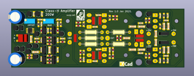
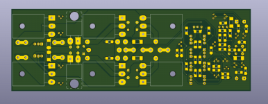
And here’s a couple of views of the PCB after routing. It’s still 160mm long and 55mm wide. I used pours to ensure the high current paths are suitably low impedance. Track width for everything up to the VAS transistors is 20mil. VAS to FET gates are 40mil. Similar logic for the rail switches. I’ve taken care to ensure I tap the feedback point from as close to the output node as possible, and done some work with the grounds to minimise any distortion contribution there too.
Clearance is mostly 20mil, but I allowed 10mil for some of the stuff in the front end where that won’t matter.
I made use of CMD-left click to figure the dissipation of everything, and that resulted in me swapping a bunch of resistors that do >100mW to MELF 0207 (1W) size. I’ve also gone for a series pair of resistors for Rf, both to keep them from getting too hot and allow an accurate 9K (20dB) gain using 4K3 and 4K7 in series.
So now to order some.
Attachments

Now that the new M1 chip is out I wonder if the older ones are going to gradually slow down due to 'clever' macOS updates.
Like IPhones and iOS
Hmmm. I still have my 2011 MacBook Air. It goes pretty well. I only upgraded to the iMac in 2017. So that’s 6 years life as a main machine, and I’m up to 4 years as a backup (admittedly I put a new battery in).
My Mac minis are all 2014 vintage. If they were slow I’d buy an M1, but they aren’t.
When I had windows machines they were junk after about 3 years.
Something that I’d forgotten about windows, but was recently reminded now that I’m paying the bills for a fleet of the damned things at work was how little the operating system does. You want to work with PDF? You’ll need to buy Adobe for that. Zip stuff? Winzip. Process words? You’ll need office, and you can’t even buy that, it’s a subscription. Plus the virus scanning.
My Mac does all that straight out of the box. And the upgrades are completely free.
Hi Suzij,
would your amplifier also work with the ancient Hitachi 2SJ50/2SK135 LatFETs?
Apparently a weird question, I know, but I've found some pairs of them 😉!
Best regards!
Can’t see why not, but it’d have to be a different PCB layout.
Something that I’d forgotten about windows [...]
A lot has changed since your 2001 WinXP 😉
ALT-leftClick
At what power level? It makes a BIG difference. Efficiency is always zero at zero output. Class A or B gets better to full power, but speech/music is not all full power, and often "efficiency" means *average* battery drain through loud and soft passages.
I hope Mr Cordell does not mind a snip. (He discusses the difference "G" or "H" but it may be beside our point.) This seems to be a 330 Watt amp. Driven to occasional speech/music clipping the average output might be 33 Watts. The AB amp is seen to be dissipating about 120 Watts. The high-efficiency amp is dissipating 40 Watts on average. Battery life, or all-day electric bill, or transformer heat, is about 3 times better for the more complicated scheme.
I would recommended EEEngine its much more efficient and you need only 1 fixed rail v/s Class H
Lateral Amplifier will be similar efficient like Class D
Suzy shouldnt you be taking the negative feedback from along the output line , currently the output is straight from the resistor commoning thus no output line ( Self distortion 7 )
Good point. I'd moved the ground pads from the far end of the board to near the middle, and moved the zobel network as well. That meant the zobel connection point was in the way.
A bit more of a shuffling sorts that. I also corrected a huge stuff-up with the 2SA1962 and 2SC5242 pinout, and while I was further mucking around I've gone with 6.35mm spade terminals for the power and speaker connections.
Thanks! I think it's looking pretty clean now.
Attachments
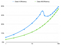
I've been trying to get a decent handle on the efficiency of this little guy. Lacking a fully designed 200W AB amp to compare against, I knocked out a quick 100W Class H, essentially by omitting the second set of lateral MOSFETs, and substituting D44H11 and D45H11 for the rail switches, plus dropping the supplies to 4x28V.
The class AB amp I use for comparison purposes is my AEM6000 based 100W one, which I designed back in 2007. It's a reasonably good amplifier in it's own right, managing much better than 0.001% THD at 1KHz all the way up to 100W.
So then I calculated power in plus MOSFET dissipation at a bunch of output power levels from 1 to 100W. The little 100W class-H absolutely blows the doors off the Class AB in efficiency terms up to 25W, which is where the HV rails turn on. After that the efficiency drops off, but in all cases it's significantly more efficient than the class AB amp.
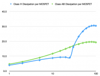
The bad news is that after 30W, omitting half the output transistors can be seen in increased dissipation per device vs the class AB. Worst case (90W out) it's just a tad over 30W per device, so well within SOA. Totally manageable as long as I size the heatsink accordingly. This is where the bit of folded tin in the 3240PE means that I can get blown up amps for cheap 🙂.
I rather like this little amp. Given that I've already done most of the design work for it I shall knock out a PCB.
The class AB amp I use for comparison purposes is my AEM6000 based 100W one, which I designed back in 2007. It's a reasonably good amplifier in it's own right, managing much better than 0.001% THD at 1KHz all the way up to 100W.
So then I calculated power in plus MOSFET dissipation at a bunch of output power levels from 1 to 100W. The little 100W class-H absolutely blows the doors off the Class AB in efficiency terms up to 25W, which is where the HV rails turn on. After that the efficiency drops off, but in all cases it's significantly more efficient than the class AB amp.
The bad news is that after 30W, omitting half the output transistors can be seen in increased dissipation per device vs the class AB. Worst case (90W out) it's just a tad over 30W per device, so well within SOA. Totally manageable as long as I size the heatsink accordingly. This is where the bit of folded tin in the 3240PE means that I can get blown up amps for cheap 🙂.
I rather like this little amp. Given that I've already done most of the design work for it I shall knock out a PCB.
Attachments

Last edited:
- Home
- Amplifiers
- Solid State
- A small Class-H Lateral MOSFET amplifier