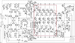
Why change the value of R119/120.
This was patrick's post on another thread:
This amp's circuit design is good. Upgrade with normal recap, replace resistor is OK.
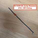
If we change a higher driver current, you will have a more warm, dynamic and punch bass performance. To do that, remove two 100R resistors R119,R120 and replace a 47R 2W connect between two driver transistors. After mod reset bias.
R119 and R120 - anything special about which 47k 2W resistor they get? Or any one will do?
Filippo
The replacement resistor is a 47 ohm 2W (not K ohm), normal 2W resistor is OK, even you just use the R119 and R120 parallel together as a 50 ohm will fit this application as well.
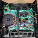
Everything arrived this morning, so I got underway.
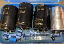
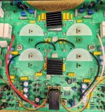
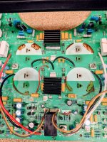
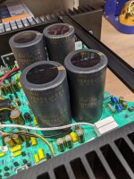
First off the filter caps are 20mm taller, necessitating relocation of the cross bar which attaches to the large heat sinks. I shortened the bar and shifted the mounting location from overtop of the filter caps to south of the caps.
I pulled the 4 filter caps and a 5th cap that had leaked. Cleaned the board with distilled water, q-tips, and a small piece of lexan to gently scrape the caked electrolytic material loose from the PCB board.
I discovered I ordered the wrong VR's ... 2MΩ instead of 2kΩ! I've updated the spreadsheet and I believe the correct p/n is Bourns 3296Y-1-202, which is
2kΩ, 1/2W, 10% provides 25 turn attenuation. 2 of them are on their way.
I have Holco H4 resistors on their way for the feedback side of the amplifier. I also replaced R119/R120 per Patrick's suggestion. Those received Vishay PR02000204709JR500.
Fuses all replaced. At this point I'm waiting on the feedback resistors to arrive, and the new trimmer pots. I have the on/off relay to replace, along with a single capacitor on that board, and finally need to install the filter pots.
I'm looking forward to the opportunity of firing this amplifier up. Thanks to the various people that have kindly taken the time to post on the thread. Most appreciated!
Filippo
Attachments
Thank you, as always. One (hopefully) last question: R119 / R120 are in the left channel? So R219 / R220 would also be changed the same?Nice job and the new gold cap is beautiful. The speaker relay contact points should be cleaned or just replace a new one for secure.
Hoping for a successful firing up of the amplifier!
Filippo
Thank you, as always. One (hopefully) last question: R119 / R120 are in the left channel? So R219 / R220 would also be changed the same?
Filippo
yes, you can confirm if they are all the same value and size.
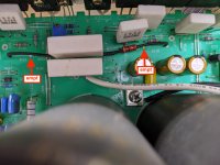
for new replaced resistor installation, you solder it on the PCB soldering side, one resistor leg solder to old resistor position which is one of driver transistor output, the other resistor leg connected to other old resistor position by extended wire with heat shrink tube protection and make sure no short circuit in the final installation.
Attachments
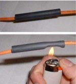
Got it.for new replaced resistor installation, you solder it on the PCB soldering side, one resistor leg solder to old resistor position which is one of driver transistor output, the other resistor leg connected to other old resistor position by extended wire with heat shrink tube protection and make sure no short circuit in the final installation.
")
Filippo
From Post #6 on this thread, https://www.diyaudio.com/forums/solid-state/333432-parasound-hca-1500-blowing-channel-fuses-mono-bridge-2.html#post5811699:
Filippo
No further information was ever posted on this thread. Curious if anyone knows what might have been done to this amplifier to increase its output capacity?I picked up my amp yesterday. Wow! I'm glad I decided to keep the amp and have Dan Horton, of Classic Audio Restoration, work on this.
It turns out that aside from the obvious shorted output devices on the left channel, from my stupidity, some of the output devices on the good side were measuring way below spec.
After just a day of running, I can say I don't miss running my Vandersteen 3A's with one amp, rather than the two in mono bridge.
One benefit of Dan's work was wpc output before clipping is higher than the spec'd 205 wpc ... it's now about 242 wpc. What helped this is that my amp must have been at some point, maybe later, in the production run where the power supply jumped from 60,000uF to 80,000uF.
I'm hoping Dan will jump in with more details. All I can say is that if you have a Parasound amp getting long in the tooth, or (partially) shorted out like mine, it is worth getting it fixed. IMHO these are great bang for the buck amps.
Filippo
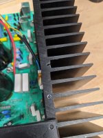
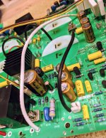
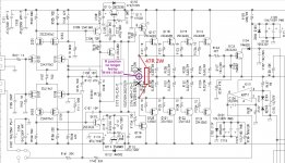
Hi Patrick, I'm sitting down to replace R119/R120 and looking at your schematic marking. I am still a bit confused. I understand that if R119 and R120 were in series, at 100R each that would be 200R, and that you recommend changing that to a 47R 2W.for new replaced resistor installation, you solder it on the PCB soldering side, one resistor leg solder to old resistor position which is one of driver transistor output, the other resistor leg connected to other old resistor position by extended wire with heat shrink tube protection and make sure no short circuit in the final installation.
But in looking at the diagram you supplied, bridging those two connections with one resistor, and getting rid of the inside connections (where you drew the "X") has me lost. There is a junction to which the electrical path flows from each of those resistors.
1) This modification would remove that junction path, correct?
2) In the new diagram, if #1 is correct, I don't understand what function the 47R "bridge" resistor now performs?
I've attached a photo to help clarify my explanation
.Thanks for your thoughts,
Filippo
Attachments
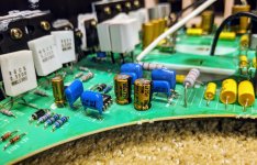
Aside from the filter caps, C021 (1000uf 25v) cap also leaked. I measured dimensions and decided to put a 35v cap in its place in hopes of giving it a bit more longevity. I wanted to provide a few photos of the fit. I have it sitting about 1/16" off the board. Tight but reasonable fit, clearing anything on the board.
Filippo
Filippo
Attachments
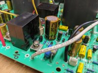
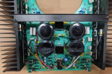
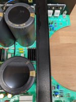
Here's how the 100mm tall filter caps fit, relative to the case. About 7-10mm space between the case and top of the caps. Well ventilated top, so I have no concerns.
Filippo
Filippo
Attachments
Last edited:
I understand that if R119 and R120 were in series, at 100R each that would be 200R, and that you recommend changing that to a 47R 2W.
original design using 200R is normal but the driver current is low, change to 47R for more higher current will make the amp performance more warm, dynamic and punch bass, you can compare by change and no change resistor
But in looking at the diagram you supplied, bridging those two connections with one resistor, and getting rid of the inside connections (where you drew the "X") has me lost. There is a junction to which the electrical path flows from each of those resistors.
1) This modification would remove that junction path, correct?
2) In the new diagram, if #1 is correct, I don't understand what function the 47R "bridge" resistor now performs?
1) yes, modification would remove that junction path
2) both connect or not connect that junction path (the output) will apply to normal amp design, it has no problem. I prefer the not connect performance.
Just feeding the thread a bit. optimationman was kind enough to provide some thoughts and insights via PM. I'll let him share on the thread as he wishes, of course.
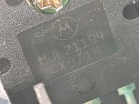
Based on his recommendation I went through and checked the transistors (power side mounted on the heat sink walls), given that I had a blown F003 fuse. They all checked out which was good. But one thing I discovered was that the transistors installed in my amplifier are not the 2SC4029/2SA1553 found in the HCA-1500 schematic. Rather my amp came with MJL21194/MJL21193.
I have not yet decided if I'm touching R119/R120, and the old Holco 47Ω feedback resistors have not yet arrived. I got enough to do a few amp projects I have in mind. I'll have some extra if anyone is looking to buy them in the USA. I got these overseas as I just could not find them here.
Filippo
Attachments
Just ran the 1500 in place of my Threshold. It is completely stock, but after finding the bias quite low on both channels I did raise it. I find the sound as reported by some a bit harsh. Making my analog sound more like a cheaper CD system. I feel that this may be due to the signal path through the pots, and mono/stereo switch ( mine stuck in stereo) with the many signal path clip connections being somewhat contributing to this hard sound. I plan on bypassing most of these point at some point. I did scope the output after bias adjustments and found the amp very quiet and the DC servo system working quite well. Let's see what a few clean up mods will do to the sound....
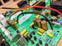
Alright, the Holco feedback resistors finally arrived so it was time to wrap up a few pieces of work. I also ran into an issue which I'll touch on in a second post. The two Holco 47k resistors went into R112 and R212.
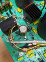
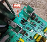
Next I went ahead and did Patrick's mod, swapping out the two 100Ω resistors per channel (R119/R120 and R219/R220) with a 47Ω Vishay, outside to outside. Everything went back together and it is ready to test.
Filippo
Next I went ahead and did Patrick's mod, swapping out the two 100Ω resistors per channel (R119/R120 and R219/R220) with a 47Ω Vishay, outside to outside. Everything went back together and it is ready to test.
Filippo
Attachments
Alright, so getting to the meat of it, got the amp back together and hooked it up to the Variac. Well the moment we fired up, fuse F003 blew. It is a 6.3A 250V slowblo, which is spec. This was the same fuse that had failed when I bought the amp. I had gone through the unit with the possibility that solder inspection, possible reflow, and replacement of some components would resolve. But to no avail. So Monday I'll chase the path and see what we find. I was told I should check the 8 transistors on the right channel. I'll report back
Filippo
Filippo
So last time fuse blown is not caused by bad big cap, it must be the circuit problem and we nedd to debug.
Before that, you take out the two fuses of the bad channel and fire up the amp to check and test the other amp channel output and sound ok or not.
After that you can check the bad channel semiconductors one by one with compare the to good channel.
Before that, you take out the two fuses of the bad channel and fire up the amp to check and test the other amp channel output and sound ok or not.
After that you can check the bad channel semiconductors one by one with compare the to good channel.
- Home
- Amplifiers
- Solid State
- Parasound HCA-1500A repair and possible upgrades