No DBT.
Want to add a correction on the thread. Optimationman had told me, in PM, that what I saw as leaks were almost certainly glue. Given the way I saw the puddling occur, I initially told him it did not seem to be glue. But having gone back and looked at some of the power caps that came off, he is correct: that brown stuff is on the sides as well, as if it came from above. Strange stuff, and very low viscosity, so it made no sense to me that it would be glue. But I can't explain why it's on the side of the caps in the pattern that it is, so go figure. Anyone know what that stuff is?
Patrick, thank you for the feedback. I'll return to the bench on Monday and we'll walk everything then - appreciate the guidance!
Filippo
Attachments
Last edited:
No DBT.
I wouldn't power it on again until you have it plugged into a DBT!
Many people are under the impression that a variac is a safety mechanism but it is at best a minimal safety mechanism. A variac will not limit the current and possible additional damage if a component is shorted, this duty is left up to the fuse which is bad especially when its a 6.3A slow blow. A DBT will limit the current and if nothing else keep it from blowing fuses. Your only indication that anything is wrong when bringing a component up on a variac is smoke or the pop of a component failing or the flash of the fuse blowing. All of these indications are bad because the damage is already done by this point. I always bring up a repaired/upgraded component with my variac plugged into a DBT. Once I've verified that there's not excessive current draw then I remove it from the DBT and bring up on the variac.
A DBT can be built up in a very simple manner. Mine is just a $3 lamp socket I bought at Home Depot wired in series into the hot leg of a cut extension cord. I have a range of bulbs from 40W to 150W. With the bias set to minimum position most Class AB amps I work on can be brought up on a 72W bulb I have.
On another note,
I just skimmed back through this thread and I do not see where you mentioned checking the diodes in the bridge rectifier on the bad channel for shorts. In my experience the rectifiers are just as likely to fail as the main caps. If you haven't already done so then you should take a minute to check the rectifier before proceeding.
Got one on the shelf. Prudent advice, most appreciated. Also thanks for the comments on the skim back through the thread: those items are on the list for Monday's testing.I wouldn't power it on again until you have it plugged into a DBT!
Filippo
I have experienced the brown adhesive before on other models that use different parts.
I haven’t seen this on numerous other amplifiers.
I haven’t seen this on numerous other amplifiers.
I'll shoot some photos of the sides of the power filter caps on Monday, so you can see how it is drizzled. Strangest stuff!
Filippo
Filippo

For the production year of these amp, most factories like to use a yellow glue to fix capacitors and connection cables. After years some of these glue become a conductor and cause short circuit problems.
To avoid the problem, people change to silicon base glue to fix parts.
To avoid the problem, people change to silicon base glue to fix parts.
Last edited:
Some of the older adhesives that were used would become corrosive over time when in contact with metal component leads. I worked on some old Kenwood amps last year that the capacitor glue had nearly corroded fully through a resistor lead and several of the leads had green corrosion on them. If you see it on component leads I would recommend that you scrape and brush it off.
Alright - I sat down at the bench and recalled that the transistors on the heat sinks were all tested. In Post #34, I wrote about transistor testing (Post #34 - Transistor testing)
Patrick just as a double check, I went back on Q111 (D/S) and Q115 (C/E) and verified no continuity, so no short.
Going to go ahead and power up and test the "good" channel.
Filippo
Patrick just as a double check, I went back on Q111 (D/S) and Q115 (C/E) and verified no continuity, so no short.
Going to go ahead and power up and test the "good" channel.
Filippo
Ok ... pulled fuses on the bad left channel. Right channel came up fine on the LBT, set bias to 15mV and watching heat sink temp slowly rise. It's at 30ºC and will do final bias adjustments when it gets around 42ºC.
Once that's done, I need to get back to figuring out what's not happy on the left channel.
Filippo
Once that's done, I need to get back to figuring out what's not happy on the left channel.
Filippo
Ok, so turns out D002 bridge rectifier is not happy, which is MB252. It's 25A/200V rated. Wondering if anyone has opinions on the replacement:
- Do I replace one or both? I'm wondering if the rectifier is prone to failure, given I'm changing one already.
- Any kind of upgrade to be considered, given heat, etc?
Attachments

Ok, so turns out D002 bridge rectifier is not happy
Maybe caused by the last bad big cap. Now you changed new cap and soon the new bridge rectifier and the amp will be fine.
I have to apologize, Looking at the schematic again I now realize I was wrong to recommend the bridge rectifier (BR) as a possible source of the channel problem. I just realized the fuse is after the bridge rectifier so even if the BR was shorted it wouldn't blow the DC rail fuse, the main AC fuse would blow instead.
Luckily bridge rectifiers are dirt cheap so it doesn't break the bank installing heavier duty units.
You know this amp is really fused in a strange manner.
Most DC rail fuses are installed AFTER the power supply not between the bridge rectifier and main filtering caps. Installing the fuses after the power supply eliminates the surge that the fuses have to endure so fast blow types can be installed. The way this amp is fused is more for fire prevention than any type of protection for electronics.
Its a lot easier to identify the problem when fused after the power supply. When the DC rails are fused after the main caps you just pull the rail fuses and see if the power supply comes up okay without the channel output boards connected.
Chamberman, I think I'm following you. Patrick also mentioned that possibly a failed power filter cap could then have smoked D002 and caused the blown fuse. Ignorantly, I may be reading the schematic incorrectly. Here's what I believe I see:
D002 failed open @ 0.015Ω, so the current is blowing through (it's become a resistor in effect?). The rectifier is toast without a doubt, so replacing that one (and both for that matter) is straightforward.
The way I understand this: the fuse is between AC power source J006A the and the load side BR D002 et al - so the BR's job is to convert DC and provide AC to the cap et al load side. If the BR load side wants to draw more than 6.3A the fuse blows:
AC transformer (J006A) --> fuses (F003 / F004) --> bridge rectifier (D002) --> caps
Sorry for being a bit winded above. I figure someone may clarify my misunderstanding 🙂.
Filippo
Attachments
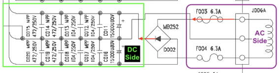
Well there's another problem too and that is d002 feeds the right channel according to the schematic. If your statement in post #51 was correct then the right channel is the good one.
#51 I got word-swapped. You are correct, of course, D001/F001/F002 would be the working side which is left channel. Bad channel is right channel D002 where F003 is blowing. Unfortunately I cannot edit and fix #51 since that post is timed out on edits.Well there's another problem too and that is d002 feeds the right channel according to the schematic. If your statement in post #51 was correct then the right channel is the good one.
Back to post #57 and my apologies for the error in #51.
Filippo
Last edited:
My schematic shows the fuses for the rails between the secondary windings and the rectifier bridges/filtering capacitors (??). Schematic dated Jan 1997. So accordingly the rectifiers are still possibly responsible for the fuse blowing.
Not sure if I have personally seen a diode fail shorted, but I'm sure it happened.
Not sure if I have personally seen a diode fail shorted, but I'm sure it happened.
Last edited:
- Home
- Amplifiers
- Solid State
- Parasound HCA-1500A repair and possible upgrades