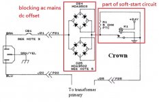
My schematic shows the fuses for the rails between the secondary windings and the rectifier bridges/filtering capacitors (??). Schematic dated Jan 1997. So accordingly the rectifiers are still possibly responsible for the fuse blowing.
Not sure if I have personally seen a diode fail shorted, but I'm sure it happened.
I just went back and looked at the schematic on the first post and you're correct the schematic he posted has the fuses before the rectifiers as well. I'm not sure what the hell I was seeing. I guess I should wait to look at those schematics when I'm on a computer at home and not squinting at my small phone screen without my reading glasses. 🙂
Rectifiers will definitely fail shorted. I've replaced a few of them over the years.
Whew ... I'm not completely daft then 🙂. Thanks guys. I'll update when the BR's arrive, get installed, and I get everything rolling again. I'm just going to check the yellow caps while everything is apart.
Chamberman, I have no idea how you looked at it on the cell phone. I have a hard time on a laptop. Last go around, I printed on two pages, assembled, and color coded lol.
Filippo
Chamberman, I have no idea how you looked at it on the cell phone. I have a hard time on a laptop. Last go around, I printed on two pages, assembled, and color coded lol.
Filippo
Chamberman, I can completely relate to the phone/sight issue. But here I take my glasses off (near sighted) and can see just fine up close, and can't see anything beyond 6 inches without those glasses.
I have used the 1500 as a driver for the woofers in a bi-amp, quick setup (stock amp), then again bypassed the pots/switch/clip connections in the same configuration. There is a definite improvement in bass definition. I will soon be using the amp solo to get an impression of the sound without the pot/switch/clips as a stand alone amp.
I have used the 1500 as a driver for the woofers in a bi-amp, quick setup (stock amp), then again bypassed the pots/switch/clip connections in the same configuration. There is a definite improvement in bass definition. I will soon be using the amp solo to get an impression of the sound without the pot/switch/clips as a stand alone amp.
Alright. Good news and bad. I installed the two BR's today, double-checked the rest of the caps in the zip code. All looked good. We then ran into another issue. I'll try to be succinct:
Filippo
- Recall the right channel was blowing F003. D002 BR was diagnosed as bad. We ordered two new BR's to replace D001/D002.
- Recall in the meantime, we pulled right side fuses, and then brought up the left channel on a DBT without issue, and ran for 30 minutes while we dialed the bias to 15mV @ 40 C.
- The VR bias pots were turned down. Fuses installed for both channels, and the power brought up on DBT.
- The DBT went bright and started pulsing, with the relay RY1 clicking at 1/2 second interval.
- No fuses blew.
- Removed right channel fuses. Started up amp again. Same thing.
- Did some looking around to verify assembly was correct, wires plugged all the way in, etc.
- Checked continuity on a variety of wires just to make sure there were no issues on hooking the board back up.
- Brought up amp again on left channel, and this time all was happy. Adjusted bias.
- I turned amp off, back on and again RY1 clicking away with DBT flashing.
- I tried pulling fuses to run channels independently. Both times, RY1 continued clicking with DBT pulsing.
- When I pulled both channel fuses, of course there is no load and RY1 does not pulse.
- In all cases, though, no fuses blowing.
- I checked inbound AC at the front board where clicking relay RY1 lives (not sure if that board has a name). 123V. When on, we get to about 20V on the other side, while RY1 clicks away.
- I went through and tested every component on that board (diode, BR, zener diode, resistors, thermisters) using a TC1 tester and multimeter. Everything tested fine. I did not test the transformer or RY1 on that board.
Filippo
Last edited:
I've had similar issues with some amps when using a DBT when there's a protect board present. What wattage bulb are you using in your DBT?
If its a low value one like say 60W then go up in wattage if you have a higher one available.
It sounds like its right on the edge of coming on with just one channel based on your left channel working and then not working.
Do you have anything connected to the speaker outputs? If so disconnect it for the initial power up.
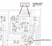
I just looked at the schematic again. Its not coming up because of the start relay circuit in the upper right hand portion of the schematic. I think a higher wattage bulb will allow enough AC volts to get the relay circuit to pull in.
If not you could bypass the start relay (RY1) contacts for a short test with the DBT.
I'd say your symptoms are a positive sign though...
If not you could bypass the start relay (RY1) contacts for a short test with the DBT.
I'd say your symptoms are a positive sign though...
The startup circuit must be something wrong.
To test the amp first, we just bypass the circuit, and just turn on the amp with out side power switch
To test the amp first, we just bypass the circuit, and just turn on the amp with out side power switch
First don't turn on the amp power switch, we direct connect the rely contact points to an outside power switch which placed after DBT.
Last edited:

The relay clicking at 1/2 second interval is very danger to the the amp, the power on/off pulses will generate high potential possible to break the things on the power supply output side.
Last edited:
Live dangerously
Maybe the cycling is due to a point where with the bulb bright, there is low enough voltage in the amp such that the power supply for the on/off relay drops below minimum hold in voltage. Once it drops out and power to the amp is turned off( bulb goes off), the applied voltage to the amp recovers, and the relay pulls in lighting the bulb, and the cycle continues. Being a dangerous kind of guy(with spare fuses) and having found what I thought was the original fault I'd be tempted to use the variac trick once.
Maybe the cycling is due to a point where with the bulb bright, there is low enough voltage in the amp such that the power supply for the on/off relay drops below minimum hold in voltage. Once it drops out and power to the amp is turned off( bulb goes off), the applied voltage to the amp recovers, and the relay pulls in lighting the bulb, and the cycle continues. Being a dangerous kind of guy(with spare fuses) and having found what I thought was the original fault I'd be tempted to use the variac trick once.
connection like this
Patrick101
That modified connection will not turn the amplifier on. Look closely at where the two pins you jumped across are going.
Fmorelli
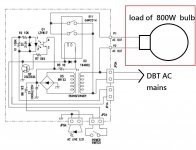
I attached a modified drawing showing how it should be connected.
With a jumper across the shown terminals the amp will always be powered on so plug it directly into the DBT and if anything is wrong unplug it to power it off.
150W bulb in the DBT should be more than enough.
I would continue bringing the channels up independently with the rail fuses pulled for the channel you want to power down. This will relieve some of the voltage drop that is causing the issue with the start circuit.
Attachments

That modified connection will not turn the amplifier on. Look closely at where the two pins you jumped across are going.
You are right!
I'm sorry my diagram in #70 was not correct, I made a correct diagram again.
https://www.diyaudio.com/forums/sol...-hca-1500a-repair-upgrades-7.html#post6126063
My sentence in #69 "direct connect the rely contact points to an outside power switch which placed after DBT" is correct.
Attachments
If the amp works ok after bypass the power on relay, next step is to fix the start circuit.
The power on/off by the relay clicking at 1/2 second interval making pulses to the power supply output and this will damage the the amp.
Better test the start circuit alone by connecting the relay output to a dummy load instead of the amp's transformer, try to find out why the little transformer cannot power the 24V relay right.
Attachments
Patrick101,
I'm almost 100% certain the start circuit problem will go away once he takes the DBT out of the circuit.
The DBT is dropping too much voltage for the start relay to pull in once the power supplies are energized. I've had this same issue in the past with other amps while using a DBT.
I'm almost 100% certain the start circuit problem will go away once he takes the DBT out of the circuit.
The DBT is dropping too much voltage for the start relay to pull in once the power supplies are energized. I've had this same issue in the past with other amps while using a DBT.
Last edited:
Patrick101,
I'm almost 100% certain the start circuit problem will go away once he takes the DBT out of the circuit.
The DBT is dropping too much voltage for the start relay to pull in once the power supplies are energized. I've had this same issue in the past with other amps while using a DBT.
Your are right! After the amp tested ok and power up without DBT will be no problem.
Fmorelli,
One other thing you could try that may be easier to do to temporarily correct the start relay issue is to drop the R3 resistance from 10ohms in the start relay circuit. I'd prob try a 10 ohm in parallel with the existing 10ohm. Dropping This to 5ohms may add enough current to the relay coil with the DBT in the circuit for the relay to stay on.
Make sure you remove this resistor and go back to the full 10ohms of resistance before you take the DBT out of circuit.
You have to realize that you only have like prob 70 - 90VAC being delivered to the amp with the DBT in the circuit. So all DC voltages after the transformers are going to be abnormally low with the DBT. This means there's not enough voltage to keep the start relay pulled in with the DBT when the relay energizes those big PS caps. That initial current surge drops the voltage across the DBT and allows the start relay to drop out. It turns into an endless loop which is why your seeing the relay clicking on/off.
The delivered voltage for the start relay must be higher than the relay coils rating and this is why they have R3 in the circuit. However if you lower that resistance for this initial test it will likely work.
Last edited:
Alright guys, I went to sleep and got up to find this whole conversation! Thanks for the thoughtful feedback. You can imagine I was slightly frustrated after yesterday's rigamarole. A healthy dose of ignorance and enthusiasm hahaha.
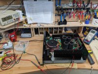
Anyway - ding ... the DBT was the issue. I disconnected both channel fuse pairs, and fired up the amp on straight wall juice. No problem. Came up with one channel, no problem. Came up with other channel only, no prob. Both channels and just happiness.
It has stabilized at 15mV @ 38°C. Next I'll hook it up to some Klipsch CF-4's and see what we have.
Thanks again for all the help, guys. Fingers crossed on the audio output!
Filippo
Attachments
Last edited:
- Home
- Amplifiers
- Solid State
- Parasound HCA-1500A repair and possible upgrades