In the good old days ") we used to reckon that less then 100 millivolts (- or +) was acceptable. Figures of just a few millivolts are as good as it gets.
we used to reckon that less then 100 millivolts (- or +) was acceptable. Figures of just a few millivolts are as good as it gets.
For example even an offset of 100mv would give a current of only 12.5 milliamps flowing in an 8 ohm load. The power dissipated is just 1.25 milliwatts in the load.
The bias current is the current that is preset to flow in the output stage under no signal conditions. This current does not flow in the load.
You haven't checked that as far as I know. To do so requires measuring the voltage across either of the 0.22ohm resistors and making sure the voltage is around 4.5 millivolts. That voltage means a current of 20 milliamps is flowing in the output transistors and that is enough to eliminate crossover distortion.
we used to reckon that less then 100 millivolts (- or +) was acceptable. Figures of just a few millivolts are as good as it gets.For example even an offset of 100mv would give a current of only 12.5 milliamps flowing in an 8 ohm load. The power dissipated is just 1.25 milliwatts in the load.
The bias current is the current that is preset to flow in the output stage under no signal conditions. This current does not flow in the load.
You haven't checked that as far as I know. To do so requires measuring the voltage across either of the 0.22ohm resistors and making sure the voltage is around 4.5 millivolts. That voltage means a current of 20 milliamps is flowing in the output transistors and that is enough to eliminate crossover distortion.
Ok thanks. That's a little technical for me but I think I get the gist in that 1 millivolt difference on the fuse between the channels is insignificant. Is that correct?
As for the voltage across R41 and R42 I get a reading of 3.8 millivolts on the faulty channel and 3.1 millivolts on the good channel. I noticed the values creep up for while on turning the amp on but they seemed to level off on these figures after around 10 minutes.
As for the voltage across R41 and R42 I get a reading of 3.8 millivolts on the faulty channel and 3.1 millivolts on the good channel. I noticed the values creep up for while on turning the amp on but they seemed to level off on these figures after around 10 minutes.
Yes, absolutely insignificant. With the fuses fitted you should see no more than -/+ 100 millivolts at the speaker terminals (in old money) and you have around 1 to 2 millivolts. All good
The voltages across the resistors sound fine so don't go altering the bias trying to improve on things.
So all seems OK and the amp should work normally...... except we haven't found a reason for what you describe in post #1 and it blowing the speaker fuse each time it was switched on.
Worth checking you haven't any loose wire strands on the speaker leads that could be causing a short. If that is OK and you also can not 100% definitely say you found a dry somewhere then (if this was mine in front of me) I would be looking to replace those two transistors I mentioned for the simple reason that parts that run hot such as those can and do fail intermittently and unpredictably.
You can test the amp now and I would try it at low volume with the bulb still in place. Don't go to loud because the bulb will severely limit current (it will light... sound to light display) and if the rails drop suddenly then the amp could do unpredictable things.
So just test at low volume and leave it playing. You can also give the PCB a good poke and prod and see if that causes any problems or whether it causes any odd noises which might point to a dry.
Ideally I would say you should also tag a low value resistor in series with the speaker just in case anything bad happens. Its up to you... a small low value part (say 10 ohm quarter watt would give good protection and the worst that might happen is the resistor goes up in smoke rather than anything else.
At the end of the day we haven't found out 'why'.
The voltages across the resistors sound fine so don't go altering the bias trying to improve on things.
So all seems OK and the amp should work normally...... except we haven't found a reason for what you describe in post #1 and it blowing the speaker fuse each time it was switched on.
Worth checking you haven't any loose wire strands on the speaker leads that could be causing a short. If that is OK and you also can not 100% definitely say you found a dry somewhere then (if this was mine in front of me) I would be looking to replace those two transistors I mentioned for the simple reason that parts that run hot such as those can and do fail intermittently and unpredictably.
You can test the amp now and I would try it at low volume with the bulb still in place. Don't go to loud because the bulb will severely limit current (it will light... sound to light display
) and if the rails drop suddenly then the amp could do unpredictable things.So just test at low volume and leave it playing. You can also give the PCB a good poke and prod and see if that causes any problems or whether it causes any odd noises which might point to a dry.
Ideally I would say you should also tag a low value resistor in series with the speaker just in case anything bad happens. Its up to you... a small low value part (say 10 ohm quarter watt would give good protection and the worst that might happen is the resistor goes up in smoke rather than anything else.
At the end of the day we haven't found out 'why'.
Thanks Mooly. As with Wayne back in 2008 I'm very grateful for all of this help. If nothing else I am learning a lot and gaining confidence.
When initially trying to diagnose I swapped the speaker over. The fuse still blew which would seem to rule out a stray wire.
I will perhaps now give it a try with of course the resistor in place to protect the speaker. Do I just put the resistor in series on the +ve lead of the speaker i.e. speaker socket > resistor > speaker wire?
Tapping the board with a plastic pen or screwdriver handle is how to do it. Apply pretty sharp taps and don't be afraid to put enough pressure on to bend the board a little. You can tap any parts as well.
Those two transistors I mentioned, if you feel them I think you will find they are quite hot. Those would be my main suspects at this point although of course anything could be responsible.
Those two transistors I mentioned, if you feel them I think you will find they are quite hot. Those would be my main suspects at this point although of course anything could be responsible.
Thanks. I definitely would like to replace Q7 and Q8 as you suggest. In reference to the 2008 thread are the 2N5401 and 2N5551 still the best replacement for these?
I will also need a bit of advice on soldering I'm afraid as I've not really done much on such intricate parts but feel free to direct me somewhere else for that if necessary
I will also need a bit of advice on soldering I'm afraid as I've not really done much on such intricate parts but feel free to direct me somewhere else for that if necessary
Best advice for soldering (and desoldering) is to use a decent ironwhich means one with a fairly large tip (my preference) as it holds the heat.
For desoldering I always use braid.
Working with SMD. How to do it without specialised tools.
The Alpha III diagram I have at the moment shows a BD139 is used for Q7 and an MPSA56 for Q8
The BD139 is a small TO126 outline flat-pak. Its worth looking what is actually fitted in your amp although there are many types that should be fine for these.
https://cpc.farnell.com/stmicroelec...dkey=https:en-CPC/CPC_United_Kingdom/w/search
The MPSA56 and the 2N devices I often mention are becoming obsolete.
I would be tempted to try a BC640 for the upper MPSA56. Its a different pinout though so you would have to gently bend the leads to fit. We do that all the time.
I assuming both these transistors are just fitted 'free' and not clamped to any heatsink or chassis work.
https://cpc.farnell.com/unbranded/b...&ddkey=https:en-CPC/CPC_United_Kingdom/search
Never buy transistors off eBay, far to many fake parts around.
Just checked on my amp. Q7 is indeed BD139 and Q8 is MPSA56. I will go ahead and order your recommended replacements therefore. Thanks for the links to these.
As for further checks, I did touch Q7 and Q8 on the faulty channel whilst the speaker was playing and they are quite warm though not hot. I imagine if the volume is increased they would become hot right? Also noticed slight scorching on the underside of the board for Q7 and Q8 which I guess would indicate them running hot.
Also did some board tapping and prodding but no adverse effects so far.
Both Q7 or Q8 are 'free' fitted from what I can tell.
Thanks also for all the soldering information. I have an Antex CS18 iron with what appears to be a 2.3mm tip (https://www.antex.co.uk/products/replacement-bits/1100-bits-for-cs-tcs-tc50/b110060/). This is the same tip it had when I bought it years ago so imagine I probably need to change that at least. However if you think it best to invest in totally new kit then I am happy to do that also.
In deference to Moody, I almost never use braid and far prefer a solder sucker such as an Edsyn DS017 or the like. Don’t get a crappy one such as RadioShack. I normally like to use a 3.2mm chisel tip in my Hakko 936 for desoldering. If I need to wick up excess solder, I do use braid for that, but after the part is removed.
Just checked on my amp. Q7 is indeed BD139 and Q8 is MPSA56. I will go ahead and order your recommended replacements therefore. Thanks for the links to these.
OK, but before you fit the BC640 you need to familiarise yourself with the pinouts. As they are free fitted I would tend to insert the base and emitter first and then gently twist the device while inserting the collector. Finally check that the leads are not touching each other. 2 seconds of a job
What you have now:
https://www.onsemi.com/pub/Collateral/MPSA05-D.PDF
And what you are fitting:
https://www.onsemi.com/pub/Collateral/BC640-D.PDF
As for further checks, I did touch Q7 and Q8 on the faulty channel whilst the speaker was playing and they are quite warm though not hot. I imagine if the volume is increased they would become hot right? Also noticed slight scorching on the underside of the board for Q7 and Q8 which I guess would indicate them running hot.
Discolouration is a symptom of normal heat (although it shows they do run quite hot) and is caused by chemical changes in the PCB material. The other channel should look the same.
The BD139 is configured as a constant current sink and all that means is that the current is constant under all conditions... it never varies. The 56 ohm in the emitter and the base/ emitter junction that is across it tells us we will see around 0.65 volts across the resistor and that the transistor under no signal conditions will see approx 35V (rail voltage) * current which is 400 milliwatts. Doesn't sound much but its pushing that little transistor hard, particularly in warm conditions. The BD139 sees the same conditions.
As the signal voltage alters the voltage across each device will alter but the current stays the same. So worst case each device can see nearly 70 volts * current which is 800 milliwatts. That averages out though because the output voltage doesn't stay in one place, it is constantly crossing the zero point altering the dissipation in each continually.
I have an Antex CS18 iron with what appears to be a 2.3mm tip (404 - File or directory not found.). This is the same tip it had when I bought it years ago so imagine I probably need to change that at least. However if you think it best to invest in totally new kit then I am happy to do that also.
The first thing to do is to be sure you note down how the originals are orientated.
Once you have done that it might be safer (to avoid chewing the board) for you to snip each device out and then unsolder each remaining lead individually pulling it with tweezers as you melt the solder. Finally use braid to clean the remaining solder and leave the hole clean and free.
Thanks for the datasheets links Mooly. Having those side by side helps enormously. You can be certain I will heed your advice very carefully when fitting.
The explanation of the the mechanics of the BD139 is very interesting and yes there is slight discolouraton on both channels. I am curious as to why these run hot. Would that be due to degradation over time?
Thanks for the soldering tips. I looking forward to perfecting the technique on something less precious beforehand!
Would you say I should be OK with the iron I have? Interestingly I just checked the Antex site and they are still selling that model after so many years (£36) so I imagine it must be reasonably OK.
As long as the iron and its tip can melt the solder quickly and cleanly on a given part then it should be fine. For these small components it should be OK but it would probably struggle on parts that soak up a lot of heat such as large solder tags or perhaps large caps with heavy duty terminals.
Have a look at this. I would personally use a larger tip here but its not a bad example. Thinking about it, a small iron and tip may not cope with braid as it sucks the heat from the tip quickly... its a long while since I used a small iron tbh
YouTube
The BD139 runs hot simply because of the power it is dissipating. The 0.4 watt dissipated in the transistors is enough for them to run hot. Same if they were resistors. A 0.5 watt resistor dissipating 0.4 watt will be very hot. There is nowhere for the heat to go apart from via the leads into the board.
The new transistors will run just as hot.
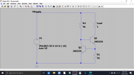
This is how the BD139 works in your amp.
The BD139 transistor is turned on (in this simulation) by R3.
As soon as the voltage across the 56 ohm reaches around 0.6 volts the second transistor turns on and begins to 'clamp' the BD139 base voltage which prevents the current rising further.
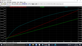
Look at the scales. The voltage goes from 5 to 50 volts. The current only changes by a milliamp or so over most of the voltage change.
The power dissipation is also shown and you can see it increases with increasing voltage dropped across the device.
The BD139 transistor is turned on (in this simulation) by R3.
As soon as the voltage across the 56 ohm reaches around 0.6 volts the second transistor turns on and begins to 'clamp' the BD139 base voltage which prevents the current rising further.
Look at the scales. The voltage goes from 5 to 50 volts. The current only changes by a milliamp or so over most of the voltage change.
The power dissipation is also shown and you can see it increases with increasing voltage dropped across the device.
Attachments
Thinking about it, a small iron and tip may not cope with braid as it sucks the heat from the tip quickly
When you say 'small iron' are you referring to the wattage?
The new transistors will run just as hot.
Oh I thought the new transistors were to deal with this issue. If not then what is the reason for changing them?
Partly the wattage and partly the tip size. A small and a large wattage iron may run at the same temperature but the small iron will be unable to keep the tip temperature hot enough when you try and solder larger items.
My reason for changing the transistors is that we haven't found a definite cause of the fault that caused the fuse to blow.
To blow the fuse at switch on means a large DC offset would be present and so the speaker drew lots of current. Personal experience (many years as a bench tech) has shown that devices of particularly the BD139 style can fail in odd but intermittent ways, and pretty much always heat related.
So they are just something that could be a hidden problem and that we can hopefully eliminate. I did also wonder about suggesting whether to replace the two drivers as well but they normally don't run hot.
The other thing of course is to look really closely and be certain there are no drys. They can be very hard to spot sometimes. Have a look at the last two images in post #1 here:
Sony CDP790 and KSS240 Restoration Project
- Status
- This old topic is closed. If you want to reopen this topic, contact a moderator using the "Report Post" button.
- Home
- Amplifiers
- Solid State
- Arcam Alpha 3 right channel fuse keeps blowing