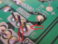
On that second image look really really closely at the middle leg of the transistor. Can you see the dark ring running around the leg where the solder is cracked. Stand back from the screen and it become clearer.
OK I just about see it i think. Really is very subtle stuff though that's why it's a little hard to grasp I think.
I will try to scrutinise as best I can but certainly can't guarantee that I will be able to pick up on all defects as clearly it relies on a lot of practice and experience. Needless to say I will persevere though because I am a dyed in the wool problem solver at heart 🙂
I will try to scrutinise as best I can but certainly can't guarantee that I will be able to pick up on all defects as clearly it relies on a lot of practice and experience. Needless to say I will persevere though because I am a dyed in the wool problem solver at heart 🙂
Btw if not too much trouble could you recommend me some suitable braid from CPC as I am putting together an order. Many thanks!
Actually I also don't know the quality of the solder I am using so probably should have a recommendation for that too.
Solder should be traditional 60:40 multicore and NOT lead free which is difficult to work with as it has a higher melting point.
Its many many years since I last had to buy any... honest... and you only need a small amount for this job and so you could try these and get two or three:
https://cpc.farnell.com/duratool/d03348/solder-wire-sn60-pb40-1-2mm-17g/dp/SD02300?st=solder
or on a reel which is better value:
https://cpc.farnell.com/multicore-solder/609997/solder-wire-crystal-511-0-91mm/dp/SD01828?st=solder
I find thicker is better tbh.
Just spotted this:
https://cpc.farnell.com/duratool/d03346/solder-wire-sn60-pb40-0-7mm-50g/dp/SD02298?st=solder
Braid... with a big iron I always go for thicker braid but I think thinner will suit you better.
https://cpc.farnell.com/servisol/20...1-5mm-x-1-5m/dp/SASOLDAMOPSTD?st=solder braid
Actually I also don't know the quality of the solder I am using so probably should have a recommendation for that too.
If its old and multicore (with flux in it) then its probably fine. Solder has become a topic all on its own and there are many many types to choose from but this kind of repair work needs only the old fashioned traditional types.
Fabulous. Thank you!
Well the solder I have is certainly old. May even had been from Tandy back in the day when they had shops on the high street. The tube is unmarked though so have no way of knowing what the composition is. Anyway the Duratool ones are so reasonably priced I will just order one of those to be on the safe side.
Well the solder I have is certainly old. May even had been from Tandy back in the day when they had shops on the high street. The tube is unmarked though so have no way of knowing what the composition is. Anyway the Duratool ones are so reasonably priced I will just order one of those to be on the safe side.
I agree with that advice on solder, and the braid quality is important too. It should look untarnished, more or less like freshly polished copper and in a width to suit the iron tip size and power rating of the iron. Braid needs quite a bit of heat input to make the solder "suck" efficiently and with little mucking about since that causes overheating and damage to the PCB by lifting tracks etc. You might try cleaning any oxide off really old solder before use too.
I once tried a number of cheapo braid types from China via Fleabay and wow! - what a disaster. The braid virtually unbraided itself if you tried to slide it over the joint as it filled with solder. It would divide into shreds of a few copper wire strands and then drop little beads of solder everywhere as a finale to the non-performance.
That junk is still sold, labelled with Japanese brands like Goot and Hakko but it's a discredit to both if they had anything at all to do with these products. Don't buy junk on the assumption that it will still work acceptably. Some fakes just don't work at all.
Last edited:
Sorry for the delay in updating on this - been away for a few days.
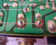
I have tried to look for dry joints as best I can and while there doesn't appear to be anything obvious I certainly couldn't say for sure that there aren't any.
In the meantime I'm still putting together an order for CPC and thought I might as well order Q11 and Q12 while I'm at it just in case. The are labelled as FST240 and FST239 on the schematic. Would these still be relevant or are there better replacements?
I also need to order a solder iron stand and was wondering whether one with sponge or brass wire ball is better?
Btw I was also wondering that while I am in the position of only having one channel working it is possible to have both speakers connected to the good channel?
My speakers are Mission 760i. The recommended amplifier out power is 25 - 75 W/Ch and the nominal impedance is 6 ohms. The enclosure is 2-way reflex in case that's important.
My speakers are Mission 760i. The recommended amplifier out power is 25 - 75 W/Ch and the nominal impedance is 6 ohms. The enclosure is 2-way reflex in case that's important.
I've always used a sponge and to be fair never had any problems or wanted anything different. Personal preference I guess.
The FST transistor numbers aren't anything common as far as I know. Could they be related to the BD239/240 I wonder. Manufacturers love to use obscure 'house' numbers sometimes.
They are just used as normal drivers and I think they are just normal small plastic packaged devices that are free standing on the board... yes?
If so then BC639 and BC640 would be worth a look. I would also duplicate the repair on the good channel as well if I were doing this.
Driving two speakers from one output... well it all depends how loud you take it is the answer. 6 ohm loading equates to 3 ohm when in parallel and that's considered a toughish load... but then again if you only listen at moderate volume you will only be delivering a watt or two at most. Keep it real and keep the volume within sensible limits and it will be fine.
Thanks Jaycee. Yes I noticed you mentioned that in the 2008 thread that Mooly linked to last week. I was just about to mention it actually but you beat me to it 🙂 Much appreciated!
 those look fine but study data sheets to be sure you know the pin outs.
Luckily, the FST pinouts are shown on the Arcam Alpha series general schematic. They are the same as shown on the Diodes Inc. datasheets for the ZTX types and also MPSA06/56. That doesn't imply that they are interchangeable in both driver and voltage amplifier stages, since the frequency compensation scheme is different to most other amplifliers which use conventional Miller compensation.
Attachments

Last edited:
I wouldn't really envisage any problems tbh, the output stage with it's TIP devices is pretty slow in the scheme of things and operates outside the HF feedback node takeoff. The whole amp also runs at very high gain compared to most which also aids stability.
One thing you should do though when replacing semiconductors is to turn the bias down before powering up because this is one parameter that will be different. Minimum bias current equates to minimum resistance of the preset on this design.
One thing you should do though when replacing semiconductors is to turn the bias down before powering up because this is one parameter that will be different. Minimum bias current equates to minimum resistance of the preset on this design.
Thanks Ian/Mooly. I will take heed of your bias advice Mooly but will need to ask you more about what adjusting it entails closer to the time.
As for now I need to practice soldering and de-soldering on some defunct equipment 🙂
Btw I am using the amp currently with both speakers connected to the good channel - one connected to the 'direct' terminals and one to the 'switched'. I am keeping the volume down of course as you suggested.
I'm also on the lookout for a less precious speaker that I can use as a test speaker on the good channel. I would still like to protect if possible though and was wondering whether keeping the 10 ohm resistor in would do that? I would be removing the lightbulb of course from the mains cable. What do you think?
- Home
- Amplifiers
- Solid State
- Arcam Alpha 3 right channel fuse keeps blowing