Many thanks Mooly. I really appreciate this. I will endeavour to work through things step by step and report back with updates and any questions.
Re the DBT -
In the 2008 fix Wayne has the idea of making up an IEC cable with the light in series as an alternative to soldering onto the fuse inside the amp. Would that work?
In the 2008 fix Wayne has the idea of making up an IEC cable with the light in series as an alternative to soldering onto the fuse inside the amp. Would that work?
As long as the bulb appears in series with the mains you can wire it any way you want as long as it's safe.
If there is a fuse in the amp then you can just remove it and solder the bulb across the empty fuse holder. Just make sure any bare live wires are out of the way so you can't accidentally touch them.
If there is a fuse in the amp then you can just remove it and solder the bulb across the empty fuse holder. Just make sure any bare live wires are out of the way so you can't accidentally touch them.
If you Google other terms like "lightbulb limiter" too, you'll see many ways to build up a DBTester using standard mains hardware like junction boxes, a bayonet or screw lamp socket and IEC panel sockets etc. IEC leads are in excess quantity in many homes now, so it seems good if they get some use. Beware that some ideas with mains power are downright dangerous or over the top, like a lot of DIY ideas on the 'net that nobody checks until there are serious complaints.
You'll need to incorporate IEC sockets of the opposite gender if that's how you want to connect the DBT. That is, the power in and power out sockets are made incompatible because you need to ensure that Active (live) and Neutral connections won't be transposed when you connect the power with standard IEC connecting leads. There is a potential safety issue there and you won't find commercial IEC or any other approved style mains leads with the same plug or socket at either end for such reasons.
You can see examples on old AT and ATX type PC power supplies and some power amplifiers such as Quad 306, that switch the mains power to a preamp etc. as well as the amplifier.
Thanks Ian/Mooly
Yes I have many of these types of cables so I simply cut one in half, put the 100W bulb in series on the live wire and reconnected the neutral and earth wires using a connecting block. I assuming this is what is intended.
On switching on the bulb lights up brightly for a moment and then dims to nothing as far as I can tell. I can repeat this procedure and the same thing happens each time.
I swapped the 100W bulb for a 60W and the same thing happens.
Is this normal behaviour i.e. lighting reasonably brightly for a moment and then dimming to nothing?
It depends on the current drawn normally with no signal or output. Some amps, such as Mosfet types need significant bias current, class A amps usually draw their maximum rated current constantly. Common BJT designs though, can run very cool with almost no idle current.
There can be other inefficient circuits working at their own full power all the time too, including voltage regulators, monitoring circuits, remote controls and tuners in older receivers. If their total current draw is sufficient, the bulb will have enough current flowing through it to bring it to full brilliance, where the safety feature is maxed. Up to that point, it works like a varistor with current indicator - just what we need.
There can be other inefficient circuits working at their own full power all the time too, including voltage regulators, monitoring circuits, remote controls and tuners in older receivers. If their total current draw is sufficient, the bulb will have enough current flowing through it to bring it to full brilliance, where the safety feature is maxed. Up to that point, it works like a varistor with current indicator - just what we need.
And.... If the link is correct, that is a valve/tube amplifier shown in the video. All bets are off when there are also constant heater currents to account for. Typically, a 150-250W bulb is used with guitar amplifiers too. FWIW, I would be comfortable using only a 40W bulb with the Alpha 3.
Actually by Googling 'lightbulb limiter' as Ian suggested I just found a video which at 3'40" suggests this behaviour is correct - YouTube
Just curious as to why it dims to 'nothing' given Mooly earlier indicated that it should glow at least a little.
It's as Ian says, the brightness depends on the current although it is non linear.
The resistance of the filament when cold is low, around 36 ohms for a 100W 230V bulb. So if the current drawn by the amp is low the filament has little effect and the amp sees nearly full mains voltage.
If the current rises, the filament heats and its resistance increases rapidly limiting the current. The bulb now starts to light.
It is the non linear resistance vs temperature that makes the bulb so useful to us.
I would recommend first rigging the amp up with a DBT (dim bulb tester) which does prevent lots of current flowing under fault conditions. That is just a 60 or 100 watt mains filament lamp in series with the live feed to the amp.
With the amp all back together you put the meter negative lead onto ground which will almost certainly include the metal chassis.
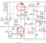
First checks are always supply voltages, we never assume anything without confirming it to be correct. With a bulb tester in circuit the voltage will be a little low (assuming nothing is drawing excess current) and so you should read PLUS 38V on the collector (middle pin) of the TIP3055 and MINUS 38V on the collector of the TIP2955.
It might be easier and safer (we don't want any slips of the probe) to measure on D3 and D4 instead... look at the circuit and you will see they are the same points.
Next measure the voltage on the speaker fuse. That should be close to zero but won't be with your fault.
Switch the amp OFF and check those two 0.22 ohm resistors. You can test those in circuit but remember they are so low in value that your meter lead resistance will add to the result. You should see 0.4 ohm or lower for each.
Next we put the black lead of the meter on the speaker fuse (you can connect it to the positive speaker socket if the fuse is intact) and then we take four readings with the power on.
1/ To the base of the TIP3055. You should see approx +0.6 volts.
2/ To the base of the driver Q11. You should read approx +1.2 volts.
3/ To the base of the TIP2955. You should read approx -0.6V
4/ To the base of the driver Q12. You should read approx -1.2V
For all faultfinding you have NO speakers attached.
Ok so I worked my way through these Mooly.
For the supply voltages I connected to D3 and D4 as you recommended and got readings of +34.4V for the 3055 and -34.4V on the 2955. I checked these against the good channel and the readings were the same.
The fuse on the good channel was indeed close to zero and on the faulty channel was 2.6mV at one end of the fuse holder and 1.5mV at the other. The fuse of course was dead so I removed it. Wasn't sure actually which end of the socket I was supposed to be testing so just did both.
As for the resistors I wasn't sure which ones you were referring to. Is it R41 and R42? If so they are both reading 0.5 ohm which match the ones on the good channel.
The other readings are as follows
1/ To the base of the TIP3055 +0.5 volts.
2/ To the base of the driver Q11 +0.97 volts
3/ To the base of the TIP2955 -0.5V
4/ To the base of the driver Q12 -1.55V
Again I wasn't sure which end of the fuse older to connect to so I took the readings with the negative probe connected to the other end and got +1 volt and -1 volt respectively.
The end of the fuseholder to use is the end that connects to the main circuitry side.
The Q12 reading seems to show a problem in that it implies that with -0.5V on the TIP2955 base and -1.55V on the driver base there is going to be just over 1V directly across the base/emitter junction of the driver.
That is to high and suggests that Q12 could be faulty.
It would be good to recheck that result and be certain and also to confirm it by doing a direct voltage measurement across B and E of that driver. Be extremely careful not to short any pins.
All the other voltages look OK.
What is surprising is that there doesn't appear to be any DC offset (high voltage on the fuseholder (as measured from ground) and that the output transistors and low value emitter resistors (R41 and R42) seem OK.
Looking at the schematic is the main circuitry side of the fuse socket the left side? I've assumed it is and rechecked measurements accordingly with the negative probe connected to that side. This gives a reading of -1V on Q12 and +1V on Q11.
With regards connecting directly across the base/emitter junction of Q12 is that simply a case of one probe on the base and the other on the emitter?
Again assuming I am now connecting to the correct side of the fuse holder I checked the voltage again on that. It's still hovering around 1mV
With regards connecting directly across the base/emitter junction of Q12 is that simply a case of one probe on the base and the other on the emitter?
Again assuming I am now connecting to the correct side of the fuse holder I checked the voltage again on that. It's still hovering around 1mV
Actually I just figured that since the fuse doesn't blow with speakers unattached I could replace it and connect to the positive speaker socket which I did. Result is the same -1V on Q12 and +1V on Q11
I just cross checked with the good channel and it is also reading -1V on Q12 and +1V on Q11. I think I misread 1.02 the first time as 1.2V
On the basis of these corrections and the cross checking it would now appear that there are so far no abnormalities. Would you agree? If so it leaves me wondering whether resetting the transistors corrected a weak joint or something. Well I live in hope 🙂
Its possible I suppose...
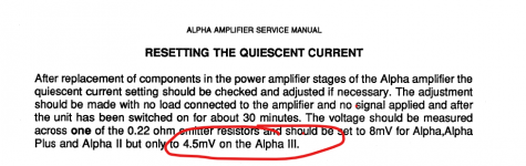
The important checks on any amp are that the speaker feed is at zero volts (and which you say it is) and also that the bias current is correct. That is calculated from the volt drop across the 0.22 ohm resistors and should be no higher than 4.5 millivolts on the Alpha III. So very low.
I would be wary tbh that all is well... although it worth testing it and checking it does perform OK at this point in time. If it does then I might suggest that the always hot running transistors are replaced as a matter of course (that is Q7 and Q8) although you should look very closely for dries on these as well.
These are the two that run hot and this is the quiescent current check procedure. Its normal for the current to be all over the place until the amp is thermally stable and up to temperature.
Attachments
Thanks Mooly
I just double checked everything again and all measurements match the good channel i.e.
I've tried the amp yet with speakers as I want to clarify these things first.
I just double checked everything again and all measurements match the good channel i.e.
- 0v across the fuse
- 1v (+/-) to the base of Q11 and Q12
- 0.5v (+/-) to the base of TIP2955 and TIP3055
- 0.5 ohm across resistors R41 and R42
I've tried the amp yet with speakers as I want to clarify these things first.
Just checked the fuse again on the lowest voltage setting. There is a slight difference between the channels. Good channel hovers around 0.3 millivolts approx while the faulty channel hovers around 1.3 millivolts i.e. 1 millivolt higher.
I should add these are MINUS readings by the way where the red probe is attached to the fuse and black to ground.
I should add these are MINUS readings by the way where the red probe is attached to the fuse and black to ground.
Last edited:
- Home
- Amplifiers
- Solid State
- Arcam Alpha 3 right channel fuse keeps blowing