There are a few other options for protection. Don't discount a low value fuse of a couple of hundred milliamps.
Another very good option is two series connected electrolytic caps (connected either plus to plus or minus to minus) to make a bi-polar cap.
Two 2200uF caps in series would equal a 1100uF equivalent and that would give decent bass response. The voltage rating of the caps need to be equal to at least the supply voltage of one rail.
The cap fully protects the speaker against DC current flowing even if the output of the amp went to the value of one of the rails. It's then just like an old AC coupled amp that we always consider as speaker safe.
Thank Mooly
Would the low value fuse go in place of the 2A quick blow fuse already in there or in place of the 10 ohm resistor?
Intrigued by the second option. How do I establish the 'supply voltage of one rail'?
Would the low value fuse go in place of the 2A quick blow fuse already in there or in place of the 10 ohm resistor?
Intrigued by the second option. How do I establish the 'supply voltage of one rail'?
The supply voltage is just the voltage of either rail which I think is around +35V and -35V in the Alpha. The speaker connects to ground and so any worst case fault could only ever put one or other of the voltages across the speaker. That is what happens with most faults in amplifiers of this type (direct coupled amplifiers).
You could replace the 2A quick blows if you wanted. One thought though... if the amplifier generates a switch on/off thump then that itself might exceed a really low fuse rating.
The caps are the most foolproof... they 100% block any DC from any fault condition.
You could replace the 2A quick blows if you wanted. One thought though... if the amplifier generates a switch on/off thump then that itself might exceed a really low fuse rating.
The caps are the most foolproof... they 100% block any DC from any fault condition.
Sure no problem. I will go down the caps route - 100% foolproof sounds good to me.
With regards rigging up an old pair of speakers for test purposes I got hold of a really old pair today. A label on the back says they are 8 ohm but the wattage is not stated. Anyway I rigged them up on both channels with volume up to the level I normally play at (low to moderate) and everything is fine. This was without the 100W lightbulb and 10 ohm resistor also. I left it playing for as long as I could bear the dreadful tinny sound i.e. about 30 minutes and again no problems.
Can anything be deduced from this bearing in mind that the possibility of it having been a dry joint on Q11, Q12, Q13 or Q14 was never entirely ruled out?
Well its up to you whether you think a dry might have been ultimately responsible or not. It may or may not have been.
The bottom line is that unfortunately we never found anything definite. Dries are always a possibility but if you have resoldered the suspect joints then any possible evidence is gone.
There is also the possibility of 'did the heat from the iron temporarily fix the issue' which can happen... again we don't know.
Dries are always a favourite but only you know whether they looked suspect or not 🙂
Thanks Mooly.
Yes it's unfortunate I wasn't able to check these components while still on the board but at that stage I knew a lot less than I do now, most notably that one diagnoses as much as possible before diving in the surgical knife so to speak. Anyway as I said lesson learnt.
Following on from before I just couldn't help trying my regular speakers after testing the old ones and sure enough they are OK also. To my novice eyes this would seem to indicate some issue with the Q11 through 14 transistors which was somehow corrected by removing and re-soldering them but as you say we will never know for sure.
Given that it may be a 'temporary fix' I will be replacing at least Q11 and Q12 on both channels once I feel competent enough to do so. If you think it wise to do Q7 and Q8 also then I will follow your advice. All of these were ordered in duplicate yesterday so I should have them within the next few days.
Best regards
Nick
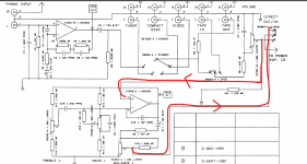
Q7 and Q8 would really be my first suspects simply because they run hot. That also made them the most likely to suffer dries:
Arcam Alpha 3 right channel fuse keeps blowing
Replacing those two and the drivers is about as far trying to second guess a possible intermittent fault can go.
If it got to that stage and the problem still randomly occurred then you would really have to be able to either take measurements in the faulty state or be able to provoke the fault by say heating and freezing a part.
To save a new thread... I have one of these that works perfectly.... but only in 'direct', disengage this and all there is is some static noise, any pointers? an opamp? thanks
Last edited:
There is an opamp in circuit but it wouldn't be the first suspect tbh. It should be easy to find with a scope though. The audio goes from the volume pot wiper to the opamp no matter what mode is selected so you should be able to trace the audio into the tone stage.
The switch just selects either the opamp output (tone control) or straight from the volume pot. Check the supplies on the opamp and trace the signal to the opamp. Maybe the switch itself is duff.
The switch just selects either the opamp output (tone control) or straight from the volume pot. Check the supplies on the opamp and trace the signal to the opamp. Maybe the switch itself is duff.
Attachments
Hello again
It's been a while but having recently acquired a decent soldering iron I am ready to have a go at replacing Q7 and Q8 as Mooly suggested.
I should add that the amp worked OK for while after my last post last year but then the right channel failed again. I proceeded to use it with with both speakers on the good channel for a while until I acquired a stand-in amp but I always intended to revisit this problem when the time was right.
My question then with regards this is what precautions should I take before attempting to replace the parts. The amp will be unplugged from the mains of course but I was wondering what else? Do I need to discharge the large capacitors even though it has been unused for quite a while i.e. two or three months at least?
I'd have to look through all the thread to get the gist of where it was all at but as to your question....
Make sure the amp is physically unplugged, not just clicked off at a wall socket. That is not just for safety but also for preventing any circulating ground currents from the iron... which to be fair shouldn't ever be an issue with circuitry like this.
No need to discharge the caps. If in doubt just measure the voltage across them. A couple of volts or less is fine. Never discharge a large cap with a short (like sticking a screwdriver across it), always use a resistor of say 1k.
Many thanks as always Mooly
I’ve taken note of your advice on removing a component and feel reasonably confident about that.
With regards fitting the new component however do you have any advice/tips i.e. how best to hold the part in place whilst its being soldered?
I’ve taken note of your advice on removing a component and feel reasonably confident about that.
With regards fitting the new component however do you have any advice/tips i.e. how best to hold the part in place whilst its being soldered?
Make sure the parts fit snugly, if the leads need preforming to fit then do that neatly with pliers, don't splay leads out as they emerge from the package. Make sure that what you fit has the pinouts correctly identified and oriented.
No special handling needed, and a couple of seconds contact with the hot iron and solder should be all that is needed to get a sound and clean mechanical joint.
I would always recommend the use of a bulb tester when powering up initially.
You could also set the bias preset to give minimum bias before switching on. That looks to be with it set to minimum resistance.
I acquired three reels of solder with the soldering iron so I am wondering which if any would be best for this?

The "Multicore" solder looks about the best out of that lot. Stay away from lead free (Sn99) solders!
Thanks Jaycee/Mooly. Actually the point about lead free solders reminded me that Mooly had given me some advice on solder previously in this thread which I was able to check back on and which was also very helpful so thanks again for that.
Anyway I've managed to replace Q107 and Q108 now. It was less daunting in the end than I had imagined and I think the result is not too bad. Before I try it though I just wanted to check something which I am a little confused by.
The board markings appear to be different for Q8 and Q108 i.e. E, B, C (Q8) and C, B, E (Q108). I am wondering why this is? Could it be a labelling mistake or am I missing something?
Please see photos attached to illustrate -
Mistakes are quite common, both on board markings and on diagrams however why are there some wire bits poking through the board??
Is that transistor (for whatever bizarre reason) mounted underneath in which case it would be correct.
You must be 100% sure you have the correct devices fitted (NPN/PNP) and that the pinouts are correct.
Is that transistor (for whatever bizarre reason) mounted underneath in which case it would be correct.
You must be 100% sure you have the correct devices fitted (NPN/PNP) and that the pinouts are correct.
Haha. Thanks Mooly. No it is the stubs from where I snipped the old one off. Sorry for the misleading image.
The new one is fitted as per Q8 markings i.e. E, B, C looking from left to right from above. I repositoned the legs of the BC640 as you pointed out so that B and C are interchanged. Also checked they aren't touching.
I'm fairly sure everything is correct so will give it try later with the bulb tester in place of course. You mentioned something about adjusting the bias though also. How do I do that?
- Home
- Amplifiers
- Solid State
- Arcam Alpha 3 right channel fuse keeps blowing