Unfortunately you don't seem to have any knowledge...Нищо от това не е вярно.
Теоретичните ви познания са малки.
it is foolish to think that it is possible to create stability with a single integrated circuit with such an input stage topology ...
communicate with those who modeled your design above ... I have nothing to talk about with you, bye-bye ...Можете ли да потвърдите твърденията си с малко теория?
Sandy, you don't seem to be familiar with the Hafler SWDT test. I recommend that you read and study the theory that is presented in the book by Jiri Dostal and confirms the conclusions of Hafler.
The effectiveness of the Hafler test was confirmed in practice by Bob Carver (I hope you are familiar with his experiment, if you are not familiar, then I recommend that you read it).
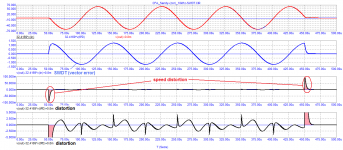
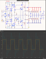
Let's carry out the Hafler test at a frequency of 10 kHz. The test showed that the peak level of high-speed distortion reaches 100 mV!
The effectiveness of the Hafler test was confirmed in practice by Bob Carver (I hope you are familiar with his experiment, if you are not familiar, then I recommend that you read it).
Let's carry out the Hafler test at a frequency of 10 kHz. The test showed that the peak level of high-speed distortion reaches 100 mV!
Attachments
This is done because the op amp needs to be stable over a wide range of gain values used, at least 1 to 20...It's best to correct it by 90 degrees. The power amplifier is designed differently ...
Sandy doesn't seem to understand the difference between op amp requirements and power amp requirements.
It is worth refreshing the memory of some of the statements of the colleagues of the forum
https://www.diyaudio.com/forums/sol...-interview-negative-feedback-post1157163.html
https://www.diyaudio.com/forums/sol...-interview-negative-feedback-post1157624.html
https://www.diyaudio.com/forums/sol...-interview-negative-feedback-post1157788.html
https://www.diyaudio.com/forums/sol...-interview-negative-feedback-post1166551.html

We are talking about the same schemes.
petr_2009's problem is that he does not understand what he is doing or what he sees on the graphs.
And he's inventing some distortions caused by speed.
And in practice, his graph shows the momentary vector distortions.
These are the sum of amplitude distortions (THDs) and frequency distortions (AFC)
In other words, the limited top frequency characteristic.
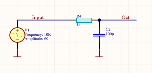
In this case, this large distortion comes from the 1k/100p input filter and the output inductance.
And above all from the fact that sine packets do not have only 10KHz frequency.
This package also contains frequencies higher than 10KHZ which these two filters and the amplifier itself cut.
And it seems to him that this is a distortion.
Many amateurs who do not understand electronics and feedbacks are mistaken in the same way.
petr_2009's problem is that he does not understand what he is doing or what he sees on the graphs.
And he's inventing some distortions caused by speed.
And in practice, his graph shows the momentary vector distortions.
These are the sum of amplitude distortions (THDs) and frequency distortions (AFC)
In other words, the limited top frequency characteristic.
In this case, this large distortion comes from the 1k/100p input filter and the output inductance.
And above all from the fact that sine packets do not have only 10KHz frequency.
This package also contains frequencies higher than 10KHZ which these two filters and the amplifier itself cut.
And it seems to him that this is a distortion.
Many amateurs who do not understand electronics and feedbacks are mistaken in the same way.
We are talking about the same schemes.
In this case, this large distortion comes from the 1k/100p input filter and the output inductance.
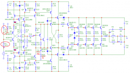
Sandi, here is the modified circuit model that was tested.
I do not understand what kind of distortion of a non-existent filter 1 kOhm / 100 pF you are talking about.
If about the input filter, then as you can see in the circuit 100 Ohm / 0 pF.
Moreover, the input signal is processed with a 100 kHz low-pass filter as recommended by Bob Cordell.
The detrimental effect of output inductance has been repeatedly mentioned by John Curl, so he tries to design such amplifiers so that they are stable without inductance. Graham Maynard has said the same thing many times. Ben Duncan also writes about the effect of inductance in his book.
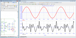
Here is one of the load tests close to reality. And I used a maximum capacitance of only 2 microfarads. John Kerl states that a reactive load can often match a capacitance of 8uF!
Sandi, everything suggests that you do not understand the ongoing processes in the amplifiers and are limited to primitive tests of models on THD in steady state.
Attachments
You couldn't see the entrance part on your pre-entry chart.
But it does not change the principle that this at the beginning and end are not any "Speed distortion"
If you want an amplifier to work well with a large capacitive load without inductiveness in the output, you will need another frequency correction.
But it will increase THD and decrease its speed
But that's the kind of amplifier that has a huge stock of both things, so that's not going to be critical for him.
The problem is that amateurs understand very little about theory and especially about feedback.
And they invent all kinds of practically non-existent problems with which they then struggle.
Last edited:
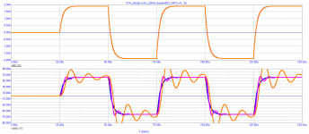
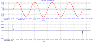
You did the capacitive load test well.
But you do not understand at all what you have simulated.
The stability of the amplifier and its feedback have nothing to do with these jitters in the capacitive load.
To see how the amplifier behaves, you need to look not after the inductance, but before it, the place where the feedback is taken.
1uH and 2uF make an LC circuit with a resonant frequency of 112KHz, which is poorly damped, and will naturally show such a picture.
But it has nothing to do with the amplifier.
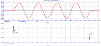
You will see the same picture without the amplifier if you directly connect the rectangular pulse generator to point FB.
See the difference between Out and Out2 in the picture.
The amplifier is absolutely stable!!
But you do not understand at all what you have simulated.
The stability of the amplifier and its feedback have nothing to do with these jitters in the capacitive load.
To see how the amplifier behaves, you need to look not after the inductance, but before it, the place where the feedback is taken.
1uH and 2uF make an LC circuit with a resonant frequency of 112KHz, which is poorly damped, and will naturally show such a picture.
But it has nothing to do with the amplifier.
You will see the same picture without the amplifier if you directly connect the rectangular pulse generator to point FB.
See the difference between Out and Out2 in the picture.
The amplifier is absolutely stable!!
Attachments
The fact that THD does not correlate with sound quality was known back in the 50s of the last century.
Hence the numerous attempts to find new testing methods undertaken by Wolf (patent SU90158), Sapozhkov (doctoral dissertation Acoustic Journal_1956_3), Otala, Hafler and many others.
We will carry out tests on loads close to real ones, i.e. on reactive loads.
we are primarily interested in what happens on the load, preferably on a real one, and not at the output of the amplifier before the inductance.
Attachments
Last edited:
Here is what Cyrill Hammer said about the need for low time Propagation Delay (tPD)
Cyrill Hammer, The Absolute Sound_ May/June 2012
https://www.moremusic.nl/reviews/passlabs/XP-30-TAS.pdf
“Perfect performance in the time domain is no less important. This is especially true of amplifiers
based on negative feedback. The theoretical concept of negative feedback is very powerful, and the
simplified mathematical equations describing this concept do hold true. But they are only valid if the design addresses the limitations of the concept. The time delay from input to output must be zero!
Obviously in real life this is not possible. There are two ways to deal with this problem. Either you just do not apply any negative feedback at all to your design (while giving up the advantages of the concept) or you do speed it up to the level (200 MHz in the case of the Soulution 700 and 710) of a few nanoseconds of time delay from input to output, where timing errors are so small that they do not have any audible impact on the sound. Once you decide to go the latter way a whole bunch of new challenges suddenly arise. Thermal conditions, stability of supply voltages, high-frequency designs, noise induction etc., etc.»
Sandy, you constantly strive to emphasize that everyone who disagrees with you is stupid and does not understand anything in electronics.
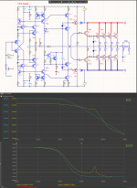
When one well-known professor in the field of radio electronics was asked the question: “why do you only listen to tube amplifiers?” He answered something like this: “when I see an amplifier with a frequency of the first pole of at least 200 kHz and a negative feedback depth of at least 40 dB, then I will listen to transistor amplifiers. But so far I do not know of such developments.”
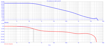
What is the frequency of the first pole of your amplifier? Here is the Bode plot of your open-loop negative feedback amplifier. As you can see the frequency of the first pole is only 200 Hz instead of 200 kHz. (1000 times lower).
p.s.
Sandy, now think and answer for yourself - why the developments of Ayre Acoustics (Charley Hansen) are recognized all over the world.
Although it is difficult for a person who blindly believes in the number of zeros after the decimal point in the THD figure and does not understand how the measurement process takes place.
Cyrill Hammer, The Absolute Sound_ May/June 2012
https://www.moremusic.nl/reviews/passlabs/XP-30-TAS.pdf
“Perfect performance in the time domain is no less important. This is especially true of amplifiers
based on negative feedback. The theoretical concept of negative feedback is very powerful, and the
simplified mathematical equations describing this concept do hold true. But they are only valid if the design addresses the limitations of the concept. The time delay from input to output must be zero!
Obviously in real life this is not possible. There are two ways to deal with this problem. Either you just do not apply any negative feedback at all to your design (while giving up the advantages of the concept) or you do speed it up to the level (200 MHz in the case of the Soulution 700 and 710) of a few nanoseconds of time delay from input to output, where timing errors are so small that they do not have any audible impact on the sound. Once you decide to go the latter way a whole bunch of new challenges suddenly arise. Thermal conditions, stability of supply voltages, high-frequency designs, noise induction etc., etc.»
Sandy, you constantly strive to emphasize that everyone who disagrees with you is stupid and does not understand anything in electronics.
When one well-known professor in the field of radio electronics was asked the question: “why do you only listen to tube amplifiers?” He answered something like this: “when I see an amplifier with a frequency of the first pole of at least 200 kHz and a negative feedback depth of at least 40 dB, then I will listen to transistor amplifiers. But so far I do not know of such developments.”
What is the frequency of the first pole of your amplifier? Here is the Bode plot of your open-loop negative feedback amplifier. As you can see the frequency of the first pole is only 200 Hz instead of 200 kHz. (1000 times lower).
p.s.
Sandy, now think and answer for yourself - why the developments of Ayre Acoustics (Charley Hansen) are recognized all over the world.
Although it is difficult for a person who blindly believes in the number of zeros after the decimal point in the THD figure and does not understand how the measurement process takes place.
Attachments
Last edited:
The internet is full of technically illiterate people who pretend to be experts, but otherwise just write nonsense.
And the ignorant, devoid of logical thinking believe them.
Instead of writing nonsense, show a Speed Distortion simulation of the RC circuit from post 148.
You obviously don't understand what group delay time is.
And you do not know that this is not at all the time for which the signal passed through the amplifier.
Anyone who can think will immediately see the dependence of group delay time on frequency.
And if this is the time for the signal to pass through the amplifier, how is it that the higher the frequency, the faster it passes through the amplifier.
If (tDT) is the transit time of the signal through the amplifier why is it the same as the transit time through a simple RC circuit with the same frequency response.
And why does 10KHz -100KHz pass in 80nS, and see 1MHz already in 13nS, and 100MHz in almost 0nS.
Unfortunately, I have not met an audio engineer who has a solid and reliable knowledge of electronics.
But very good business models are used that spread all kinds of legends to a technically mediocre audience in order to attract buyers and make money.
Attachments
The scheme I have shown here is simply to see what can be achieved in terms of technical parameters, from the good idea of the A40, which, however, is poorly implemented, due to insufficient technical knowledge.
We see that even with a small number of elements, but in an appropriate and properly connected way, we can achieve a significantly better technical result.
A simple simulation of a single circuit does not make sense.
It makes sense to compare two schemes or compare changes to the scheme to make it even better by some indicator.
So if you have such suggestions I will gladly see them and discuss them.
Although as I said I don't like CFA amps for audio.
The disadvantages are more than the only advantage, the high growth rate.
A VFA amplifier can achieve the same gain rate with better remaining parameters.
THD, PSRR.
petr_2009 simulate this circuit with your method, see what Speed Distortion you will get
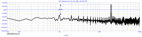
At your request, I made a test for high-speed distortion of the input RC filter.
I want to draw your attention to the fact that the test of your amplifier was made at C1 = 0 pF.
Here are two tests:
the first with pre-processing of the signal with a low-pass filter = 100 kHz (as in DIM-100)
the second with pre-processing of the signal with a low-pass filter = 30 kHz (as in DIM-30)
Attachments

Sandy, who among the developers understands what a group delay is, he indicates this parameter in the technical characteristics of the amplifier. Well, you really don’t seem to understand ... you constantly strive to be nastyYou obviously don't understand what group delay time is.
Attachments
I realized that you simulated the amplifier without the input RC circuit and I even wrote to you that in practice this is not a problem, just your Speed Distortion. they will be even bigger.
So did you draw any conclusions from the RC circuit simulation. There is no feedback with her. and in practice she also has the same invented Speed Distortion.
Well, it's normal for manufacturers to look for any way to attract illiterate customers, even by writing completely irrelevant audio parameters.
Show me one electronics textbook that mentions tDT as a feedback problem in any kind of amplifier.
tDT is only a problem when passing frequency or phase modulated signals through filters.
Because after the demodulation of such signals, the linear ones (frequency distortions) become non-linear ones (THD).
But these are things far beyond the technical knowledge of audio designers.
You may have noticed you are the only one who tries to argument with Petr2009. More precisely: The last one. All the others have given up long time ago.I realized that you simulated the amplifier without the input RC circuit and I even wrote to you that in practice this is not a problem, just your Speed Distortion. they will be even bigger.
So did you draw any conclusions from the RC circuit simulation. There is no feedback with her. and in practice she also has the same invented Speed Distortion.
Well, it's normal for manufacturers to look for any way to attract illiterate customers, even by writing completely irrelevant audio parameters.
Show me one electronics textbook that mentions tDT as a feedback problem in any kind of amplifier.
tDT is only a problem when passing frequency or phase modulated signals through filters.
Because after the demodulation of such signals, the linear ones (frequency distortions) become non-linear ones (THD).
But these are things far beyond the technical knowledge of audio designers.
I don't take it as an argument.
The man is clearly not a specialist in the field of electronics, I have been engaged in design work in this field for more than 50 years.
And with far more complex things than audio amplifiers.
I'm just struggling to explain otherwise basic things to him, hoping he'll still understand something.
It is precisely this misconception (tDT) and feedback that I have had many arguments with electronics engineers.
They even have a hard time understanding this matter.
- Home
- Amplifiers
- Solid State
- Apex A40 fundamental improvement. (Sandy)