An externally hosted image should be here but it was not working when we last tested it.
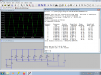
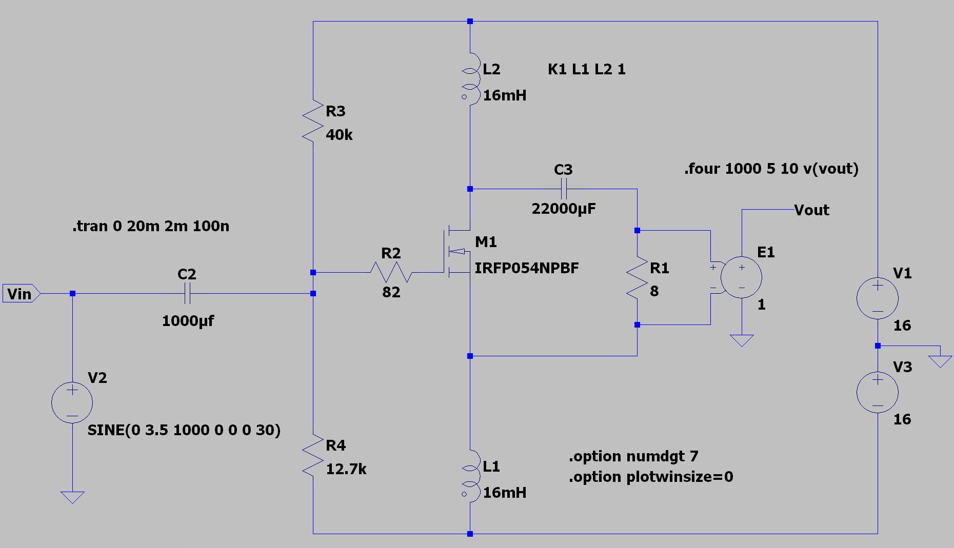
There are some things I would like to point out with the schematic above:
C2 and C3 does not need to be that large. I use very large values to avoid problems in the simulation model. It is not needed in real life. For midrange and up C2 (input capacitor) does not need to be any larger then 10 uF, and C3 can be 1000 uF or so.
I would also increase the values of R3 and R4 to 200k and 50k to avoid negative feedback in the audio range. I would either parallel a few devices, lower the voltage from the power supplies or lower the amount of current running trough the device. The IRFP054N might be a tough device, but running it at or above 50 watts of continuous dissipation is a bit harsh. It will take it with enough cooling but it will shorten its lifetime substantially. It might however sound better while it lasts, so if you want to live a little on the edge and keep a few spare parts laying around then it is a valid way to go.
An externally hosted image should be here but it was not working when we last tested it.
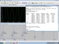
There are some things I would like to point out with the schematic above:
C2 and C3 does not need to be that large. I use very large values to avoid problems in the simulation model. It is not needed in real life. For midrange and up C2 (input capacitor) does not need to be any larger then 10 uF, and C3 can be 1000 uF or so.
I would also increase the values of R3 and R4 to 200k and 50k to avoid negative feedback in the audio range. I would either parallel a few devices, lower the voltage from the power supplies or lower the amount of current running trough the device. The IRFP054N might be a tough device, but running it at or above 50 watts of continuous dissipation is a bit harsh. It will take it with enough cooling but it will shorten its lifetime substantially. It might however sound better while it lasts, so if you want to live a little on the edge and keep a few spare parts laying around then it is a valid way to go.
I actually have 470 uF for both C2 and C3.
R3 and R4 is a 25 turn 50 kOhm trimpotentiometer, I guess that I have can have some fixed resistors as well to get the total resistance ladder up.
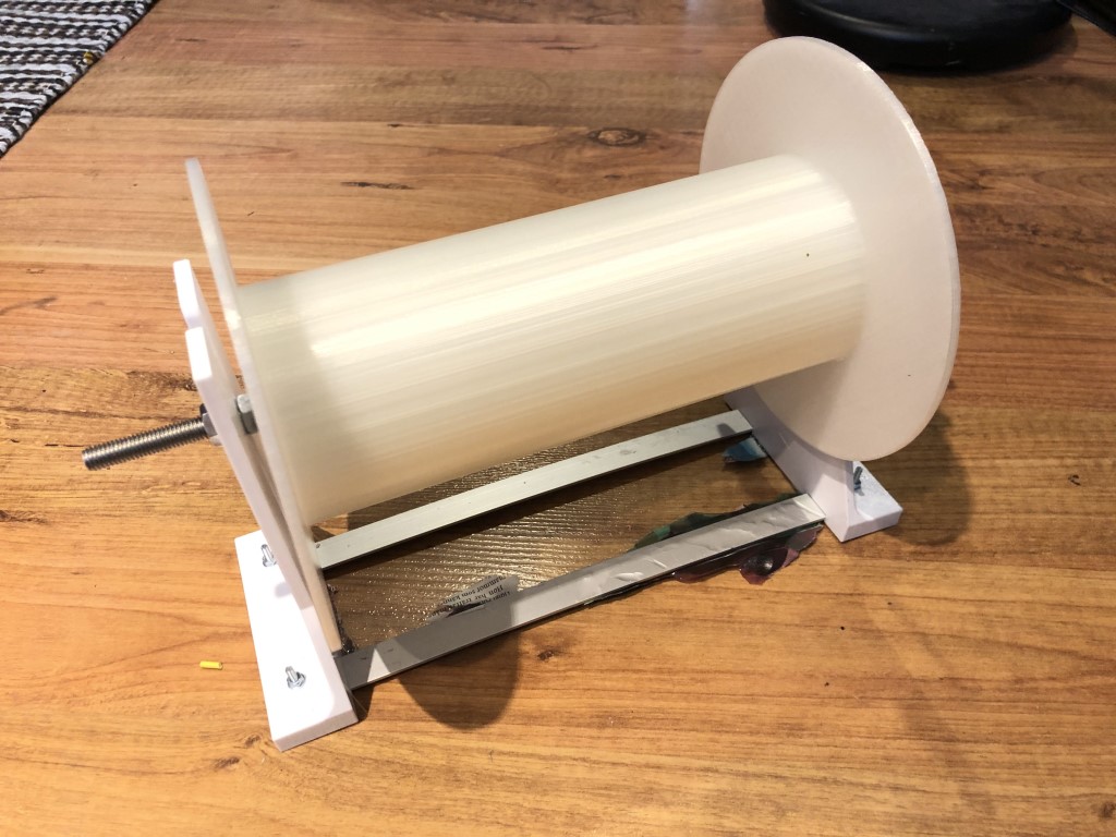
Nice forearm burn! (if you don´t have a coil winding machine of some sort).
I am really looking forward to hearing your impression once all 4 channels are up and running. I believe your AMTs will reward you with a whole new level of detail, resolution and presence (something they already excel at).
Their remarkable ability to reproduce complex signals and sharp transients with ease really impressed me!")
This helps:
An externally hosted image should be here but it was not working when we last tested it.
As long as the wires doesn't tangle it is just to turn the coil former.
Rds on is only the minimum resistance of the chip when fully open. It depends on several factors such as voltage rating, chip size etc...
IRFP7430 is a very large chip, doped for very low Vds (Volt Drain Source) rating.
It does however have an abysmal Safe Operating Area as seen in the graph below.
View attachment 788848
It is intended for switching where it is fully open or fully closed.
The IRFP7430 can only take 3 ampere with 10 volts between drain and source before you get hotspots on the large chip. This will create a thermal runaway and destroy the device if pushed beyond those limits.
This problem is easily solved by cascoding the device so it operates at lower voltages between drain and source. It can take 20 ampere at 5 volts D-S.
Last edited:
How do I accomplish the V3 voltage source?
https://www.kjell.com/se/produkter/el-verktyg/stromforsorjning/natadaptrar/ac-dc-natadaptrar/fast-utspanning/switchad-natadapter-12-v-(dc)-7-2-w-p44717
I am sure there are cheaper options. This is only meant as an example. Any small switched 12 volt power supply or small 12 volt battery can be used. The power needed is so low that a series of small batteries will loose their power due to age before being depleted due to usage.
Ok.
I think I'll go for the battery option then.
The thought of having leads from an external power supply connected to the loudspeakers scares me a little.
Rds on is only the minimum resistance of the chip when fully open. It depends on several factors such as voltage rating, chip size etc...
IRFP7430 is a very large chip, doped for very low Vds (Volt Drain Source) rating.
It does however have an abysmal Safe Operating Area as seen in the graph below.
View attachment 788848
It is intended for switching where it is fully open or fully closed.
The IRFP7430 can only take 3 ampere with 10 volts between drain and source before you get hotspots on the large chip. This will create a thermal runaway and destroy the device if pushed beyond those limits.
This problem is easily solved by cascoding the device so it operates at lower voltages between drain and source. It can take 20 ampere at 5 volts D-S.
I cannot see the attachment but I got the "Maximum Safe Operating Area" figure 10 from the IRFP7430 datasheet and the curve complies with your figures.
I've ran in to some issues with the circuit:
At power up, the current through L2 is very high.
It stabilizes after a minute or so.
If I raise the bias from a off state to the linear region and get a decent THD of -60 dB, I get a current through L2 round 3 A.
If I now cold restart the circuit, I get a heavy distorted signal; the positive waveform is chopped off.
The only way to get back, is to turn down the bias to off and then turn it up again.
To me it seems then in both cases above, and pardon me for not understanding something that probably is obvious to you guys, that the bias voltage is "floating around" at cold start so the MOSFET is fully enhanced.
It seems strange to me if this has to do with that I'm running the circuit with bipolar power supply.
I get the same if R3 is connected after L2, that is at the drain.
An externally hosted image should be here but it was not working when we last tested it.
At power up, the current through L2 is very high.
It stabilizes after a minute or so.
If I raise the bias from a off state to the linear region and get a decent THD of -60 dB, I get a current through L2 round 3 A.
If I now cold restart the circuit, I get a heavy distorted signal; the positive waveform is chopped off.
The only way to get back, is to turn down the bias to off and then turn it up again.
To me it seems then in both cases above, and pardon me for not understanding something that probably is obvious to you guys, that the bias voltage is "floating around" at cold start so the MOSFET is fully enhanced.
It seems strange to me if this has to do with that I'm running the circuit with bipolar power supply.
I get the same if R3 is connected after L2, that is at the drain.
The input time constant is about 10 seconds. (Why so long??)
The intended gate bias is 8V above the *negative rail*. But the input cap starts it at "ground" which is 16V above the negative rail. Yeah, the MOSFET turns ON, hard, for many-many seconds.
I see no way to even estimate MOSFET idle current except manual trimming.
Are your coils coupled?
Do they have any DC resistance?
Do you need to put such large images embedded in the thread?
Attachments
The input time constant is about 10 seconds. (Why so long??)
The intended gate bias is 8V above the *negative rail*. But the input cap starts it at "ground" which is 16V above the negative rail. Yeah, the MOSFET turns ON, hard, for many-many seconds.
Then I understand, thank you.
Apart from having a DC coupled input, is there another way of solving this?
The input is in reality driven by a preamplifier consisting of an opamp with 12 times gain.
In reality, the input capacitor is not that large.
Yes, they are coupled. See the dots and the LTSpice K1 L1 L2 1.I see no way to even estimate MOSFET idle current except manual trimming.
Are your coils coupled?
Do they have any DC resistance?
Their DC resistance is 1.2 ohms each.
Do you need to put such large images embedded in the thread?
I publish also on other forums that cannot upload pictures, so it's a kind of sometimes copy/paste the same content.
But I still get a clipped output at power up.
After waiting for more than a minute, it all looks good though.
It seems that the clipping has to do with ground levels from the measuring system.
With a conventional PSU (toriod, bridge, capacitors) I get a large amount of hum; it is after all 3A out of the toriod.
I could get some switched PSUs instead.
Any thoughts?
I could get some switched PSUs instead.
Any thoughts?
My Mean Well LRS-150F-12 is quiet, stable and reasonable low noise. Short circuit and over temp protection is nice.
I had some time to fool around in LTSpice today and I wanted to test 6 parallel IRFPS3810 in a SLAPS amp with some real power.
55 watt output into 8 ohm with very little distortion. I calculated a rough guesstimate what inductance and series resistance 2 x 200 meter of 2,5 mm2 cable could give.
I know this is just a simulation and as such should be taken for just that. It does however indicate a nice level of potential performance. Nelson Pass seems quite positive to the IRFPS3810 device. It does have a nice triody character and a large usable safe area of operation.
Attachments
Sweet! But not an a single 12 V PSU I guess?`
Too bad that the IRFPS3810 are a little bit costly, it would be nice to have 55 W to drive my bass speakers with.
I guess also that you'll have to quite a few as you need to match them as well.
What does SLAPS stand for anyway?
Too bad that the IRFPS3810 are a little bit costly, it would be nice to have 55 W to drive my bass speakers with.
I guess also that you'll have to quite a few as you need to match them as well.
What does SLAPS stand for anyway?

From:
https://pdfs.semanticscholar.org/a865/65635b6ba8a41b8be02c0c9e0d36d6c579be.pdf
M.J. Hawksford about feed forward error correction.
A great article.
not an a single 12 V PSU I guess?
No. 48 Volts and almost 6 ampere of current. 28 watts of heat from each device.
4 channels of this amp will keep your house nice and warm throughout our cold winter months up here in the north.
> How come again that the output swing can be greater than the power supply rail voltages or even above the voltage drop over the coils?
This is a Choke Loaded amplifier.
Works about the same as a Transformer Coupled amplifier, the best example is a single ended tube amp. Say the supply is 300V. Choke(transformer) DC losses are small, so it idles with say 280V across the tube. At amplifier power-up the choke core is filled with flux. When tube turns on, it pulls the choke toward zero. When tube turns off, the stored flux kicks the choke *above* 300V to something near 600V (typically 500+V in a tube amp).
In your plan with a 12V supply, the two chokes idle at (we hope) less than a volt drop. Transistor turns on, each pulls-in for about 6V drop each. Transistor turns off, they kick about that same 6V *beyond* the supplies.
Excellent explanation, PRR!
Here's by the way the first official play with the "one FET" at a small diy gathering this weekend. The two diy loudspeakers were coupled in parallel with no filter involved.
The two circuit boards are the +/-12 VDC PSU for the opamp and the opamp itself. The opamp is a summer with 12 times gain and with the bias voltage as one input.
- Status
- This old topic is closed. If you want to reopen this topic, contact a moderator using the "Report Post" button.
- Home
- Amplifiers
- Solid State
- SLAPS for SLAM!