The effect depends very much on your speakers. If your AMT panels have an non linear (asymmetric) Bl curve causing a second harmonic distortion component then a reverse asymmetry second harmonic component from the amp should give a distortion reduction.
The only way to know how large effect you get is to measure it in a real world setting.
You can tune this effect by varying the current through the devices and the voltage from the power supplies. The transfer curve of the devices and the number of devices can all effect the amount of second harmonic asymmetry cancellation.
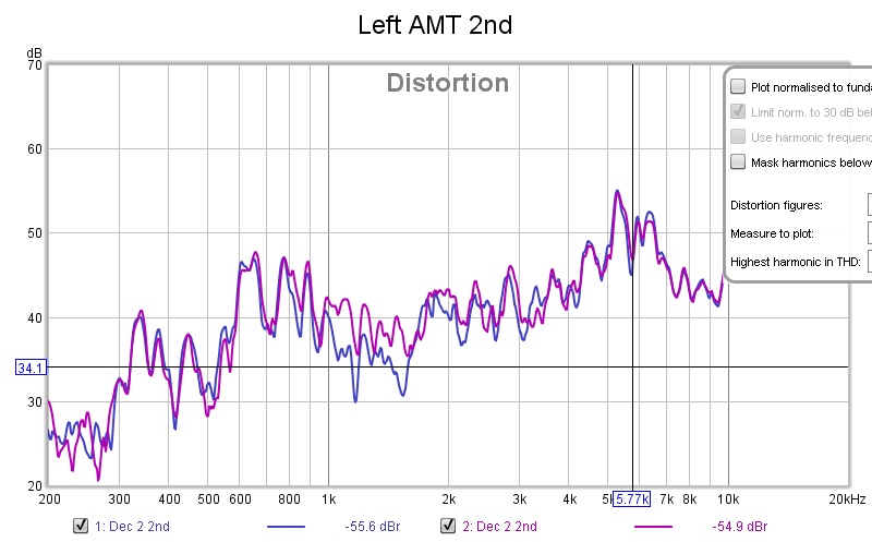
The difference in distortion proved to be systematic and not negligable.
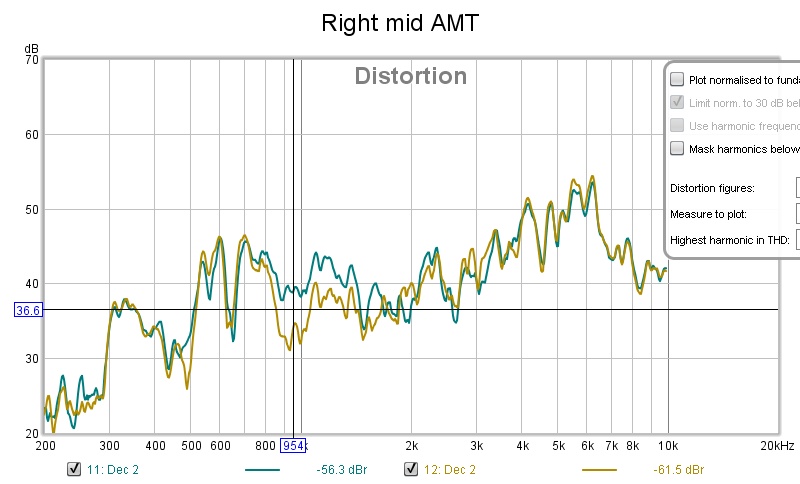
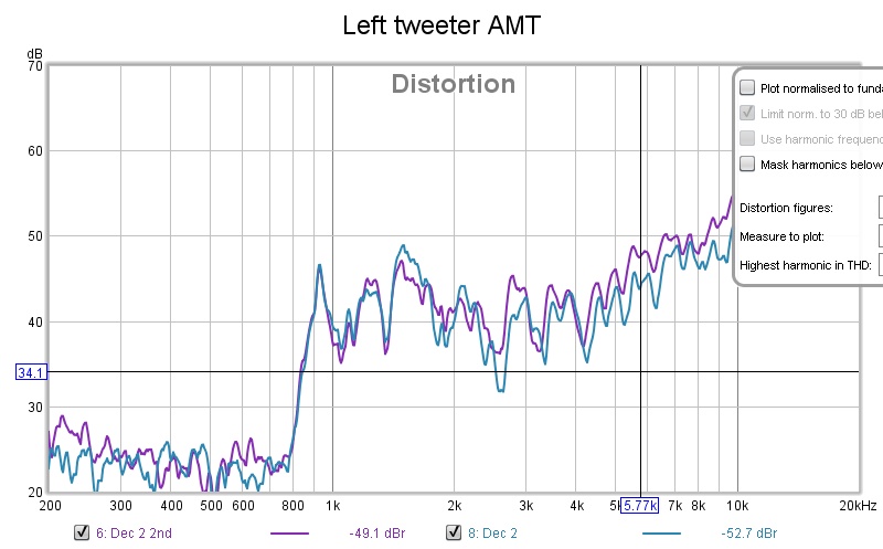
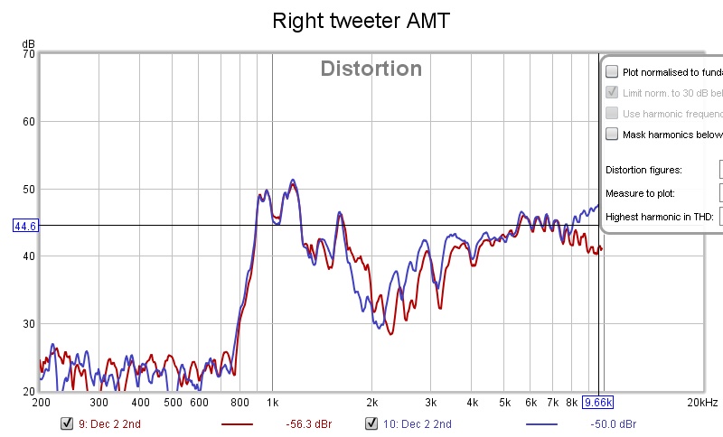
All measurements with a calibrated UMIK-1 at 1 W/ 1 meter.
For the mid AMTs quite different from 800 Hz to 1500 Hz:
For the tweeter AMTs the difference is smaller but still significant from 2500 Hz:
In all plots above, the non-reversed has the lowest distortion.
All measurements with a calibrated UMIK-1 at 1 W/ 1 meter.
For the mid AMTs quite different from 800 Hz to 1500 Hz:
An externally hosted image should be here but it was not working when we last tested it.
An externally hosted image should be here but it was not working when we last tested it.
For the tweeter AMTs the difference is smaller but still significant from 2500 Hz:
An externally hosted image should be here but it was not working when we last tested it.
An externally hosted image should be here but it was not working when we last tested it.
In all plots above, the non-reversed has the lowest distortion.
Last edited:
Nice measurements! 
Can you measure them at different power levels?
I would guess that the second harmonic of the AMT will increase quite fast with increasing power levels due to their compression ratio (surface area of the sound generating ribbons/radiating surface area seen outside the AMT).
The SLAPS does not increase distortion at the same rate, so second harmonic cancellation will peak at some spl. This is where you want to "tune" the amp to the AMT by varying the current, voltage and choice of mosfets.
Regards,
Johannes
For the mid AMTs quite different from 800 Hz to 1500 Hz:
And without making anything else worse!
I thought that the effect was going to be more pronounced, but your AMTs seems to be very linear and low distortion (which is easily heard) (and this is partly why I asked about different sound pressure levels).
Have you listened and compared the subjective experience between reverse polarity and normal polarity?
I would guess you might have a slightly more "forward", energized and in your face kind of reproduction one way and a slightly more laid back and "deeper" reproduction with more focus on details the other way. This difference might be very subtle since the over all THD level seems to be very low from both the amps and the AMTs.
Thanks for posting detailed measurements and lots of information. 🙂
Regards,
Johannes
What's the buzz?
I hear a ever so slightly buzz at the sweetspot.
I have only small ferrite beads around the DC power cables from the PSUs and of course reservoir capacitors (22000 uf).
Any suggestions to mitigate the buzz?
I hear a ever so slightly buzz at the sweetspot.
I have only small ferrite beads around the DC power cables from the PSUs and of course reservoir capacitors (22000 uf).
Any suggestions to mitigate the buzz?
Careful "star" grounding.
Keeping every ground lead as short and low resistance as reasonably possible (4mm2 cables). Move the switched power supplies away from the large coils (coils are excellent antennas!).
Keeping the amps away from other power cords if possible.
Ground the power supply casing.
Try to hunt down any ground loop and use shielded cables for all low level signal (but terminate only in the star ground).
Careful "star" grounding.
Keeping every ground lead as short and low resistance as reasonably possible (4mm2 cables). Move the switched power supplies away from the large coils (coils are excellent antennas!).
Keeping the amps away from other power cords if possible.
Ground the power supply casing.
Try to hunt down any ground loop and use shielded cables for all low level signal (but terminate only in the star ground).
I think I've already done that.
Here's how the buzz sounds.
You'll probably need to turn the volume up to hear it.
Apart from the noise, there's a cyclic pattern.
The noise I can live with as it is not audible from sweet-spot anyway, but not the cyclic pattern is really annoying..
I would guess it comes from the switched power supplies.
If that is the case you could test with a common mode choke after the switched powersupplies and before the filtering capacitors. It is easy to wind 2 x 10 meters of 2,5 mm2 cable to an air core bifilar choke on a small piece of plastic tubing or something similar.
I have not heard this from my different versions of this amp.
Do you have some small capacitors very close to the OP-amp to stop it from oscillating?
It would be unfortunate if you have to apply for a transmission permit in AM band in order to use these amps. 😉
Analog radio- Myndigheten for press, radio och tv
I would guess it comes from the switched power supplies.
If that is the case you could test with a common mode choke after the switched powersupplies and before the filtering capacitors. It is easy to wind 2 x 10 meters of 2,5 mm2 cable to an air core bifilar choke on a small piece of plastic tubing or something similar.
I have not heard this from my different versions of this amp.
Do you have some small capacitors very close to the OP-amp to stop it from oscillating?
It would be unfortunate if you have to apply for a transmission permit in AM band in order to use these amps. 😉
Analog radio- Myndigheten for press, radio och tv
I will check the SMPS standalone for the low frequency noise.
Yes, I have 100 nF across the rails of the op-amp; not involving ground.
Did you experience this problem with the early prototype that you showed at the DIY-gathering earlier this fall?
I have an oscilloscope which I can bring over if you want to go hunting for noise, oscillation or LF-instabilities? Once we see the waveform and the frequency it should be quite easy to figure out where it comes from.
Regards,
Johannes
I have an oscilloscope which I can bring over if you want to go hunting for noise, oscillation or LF-instabilities? Once we see the waveform and the frequency it should be quite easy to figure out where it comes from.
Regards,
Johannes
Did you experience this problem with the early prototype that you showed at the DIY-gathering earlier this fall?
Regards,
Johannes
No, but without the chokes on the power cables, the power supply I used then was quite noise.
The loudspeakers used then wasn't as sensitive as my AMTs and the environment was quite noisy as well.
I cannot test now with that power supply as it only has 3.2 A.
I have an oscilloscope which I can bring over if you want to go hunting for noise, oscillation or LF-instabilities? Once we see the waveform and the frequency it should be quite easy to figure out where it comes from.
Regards,
Johannes
No need, I have both an analog and a digital oscilloscope. (But you are of course welcome to listen anyway)
The only thing I've seen so far is a 100 Hz 5 mVrms residue.
The waveform is quite spiky with a lot of high frequency ringing, but a 10 nF capacitor across each power reservoir capacitor softens it a bit.
With that fix applied, the noise level actually went down a bit but the noise changed its characteristics.
What I think is going on is that I get inter-modulation on the 100 Hz due to for example the phase shift that the coils gives.
I'll modify the other three as well and I'll see tonight (in the quiet night) if it still annoys me.
Last edited:
Rotate or/and turn the switch-supplies?
//
Yeah, first I can test with external SMPSs.
Interesting build I must say. Especially the DIY chokes.
I have a question for those who are good at theory.
How do you determine required inductance for this duty?
What effect would cause in-series resistor (for increasing DCR?
To be more specific - if I would take 10 coils, each of.. Say 1/10th of inductance specified in this topic, each with in series resistance of 33ohm.. Would this simply reduce any purpose of inductor load? (Assuming that paralleling inductors lessens the total inductance).
My point in trying to figure this out lays in local mass properties of polarized energy.
How do you determine required inductance for this duty?
In my case it all started with testing how much performance I could get out of 2 x 100 meters of 1,5 mm2 cable that I already had laying around.
I wound a large bifilar choke with all that cable and started to play with it in different circuits.
I would guess that the series resistance in the cable is mostly a restive loss. It helps with getting a stable bias, but I would prefer a lower DCR if I had the money. 5 mm diameter magnet wire is quite expensive (and a pain to work with without the proper tools).
Yeah, first I can test with external SMPSs.
Placing the SMPSs half a meter away reduced the buzz a lot.
I still get some stochastic noise though.
Yesterday I got the opportunity to listen to Solhagas AMTs and SLAPS, and I am mighty impressed!!!
The definition, the lightning fast sharp transients and the organic effortless "here and now" character of these amps driving the AMTs are very convincing and addictive.
We listened to a great recording of Jeanette Lindström & Steve Dobrogosz and the song Never let me go, and the piano had a very effortless and natural presence with all the physical and tactile energy that our piano in our living room displays while my wife plays on it.
It is all these small, complex, non-sinusoidal and transient peculiarities in the wave shapes that if reproduced correctly gives the sensation and impression of an effortless "here and now" that normal direct radiating hifi drivers and global negative feedback amps never seems to be able to reproduce. I have never heard a dome driver coming close to this level of definition.
It was a very inspiring, and I want to thank you Solhaga for this opportunity to listen to your great sounding sound system. It is truly some unique!
Regards,
Johannes
Thank you for the visit, Circlomanen.
It was really good to have a reality check.
It is I that shall thank you for the excellent SLAPS designs!
A note on the low frequency inter-modulation.
It is most probably due to that I'm using two SMPSs and whatever individual residues there are from each of them.
There's then a slight difference of the presumably high frequency converters making the inter-modulation.
Regarding the stochastic noise I heard before, it was due to dead op-amp leaving the gate open.
It is still a good idea to clamp the op-amp's output to ground using a 33k resistor; the noise level was reduced significantly.
- Home
- Amplifiers
- Solid State
- SLAPS for SLAM!