Regarding the noise level/inter-modulation:
I have now tried:
The first two made no change, the third reduced the inter-modulation as expected but not the actual noise level itself.
Measuring with digital sound level meter as close as possible to the speaker, I get 34 dBA when the amplifier is off, and 37 dBA when it is on.
With an ordinary DMM, I get 1-2 mVrms across the speaker terminals.
It is of course not measurable at sweet-spot but still audible, or rather noticeable when I shut the amplifier off.
I reckon I will have to live with this. After all, the computer in the another room makes more noise.
I have now tried:
- to supply the op-amp via 7812/7912,
- a direct bias voltage from the +/- 14 V rails,
- and a single 28 V SMPS.
The first two made no change, the third reduced the inter-modulation as expected but not the actual noise level itself.
Measuring with digital sound level meter as close as possible to the speaker, I get 34 dBA when the amplifier is off, and 37 dBA when it is on.
With an ordinary DMM, I get 1-2 mVrms across the speaker terminals.
It is of course not measurable at sweet-spot but still audible, or rather noticeable when I shut the amplifier off.
I reckon I will have to live with this. After all, the computer in the another room makes more noise.

A pair of these for each double supply or a single coil for single supply should minimize noise very effectively.
1 mH 0,8 mm diameter magnet wire cost 53 kr at Hifikit.

This is the exact power supply that I used in several of my experimental SLAPS-prototypes. My single channel SLAPS where dead silent with my ear very close to my Dayton PS95-8 wide band drivers or my HROAR10 subwoofer.

There are a couple considerations for using a swmps
1) Generally products have only one polarity, so you have to get 2 to make
a bipolar supply. When you use two supplies, you may find yourself listening
to a beat frequency noise coming out of the speakers which is at the
difference frequency of the two switchers. It wanders around in frequency.
This leads to:
2) You need to filter the rails for the noise out of the switchers, and you
usually can't just do it by sticking big capacitors on the rails - some
switchers sense the high current at low voltages and decide that there is
a short. Others will limit the current until the caps are charged. A strong
possibility is to make a follower filter with a cap multiplier which filters and
has a low current at initial turn-on, but you will give up a couple volts
doing it.
If you're not trying to be too cheap, take a look at Meanwell supplies
available from TRC
So we got a proper name for it: beat frequency.
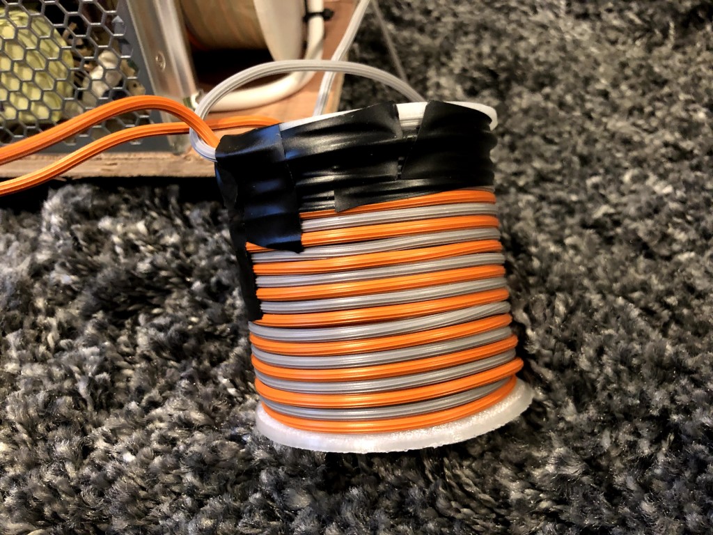
And, the self-made coil that you suggested earlier Circlomanen of 2 times 10 m of 1.5 m2 bifilar coils between the +/- SMPS and the filter capacitors works!
Still a audible hiss close to the speaker, but not detectable beat or hiss at sweet spot.
A lot cheaper and a lot lower resistance.
And a lot bulkier too!
But as we say at work: "It's not a bug, it's a feature."
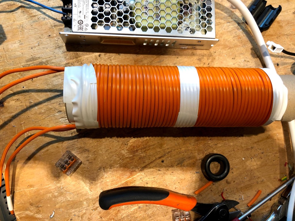
A 3D-printed coil former looks nicer:
So I need to redo the layout to get the choke in place.
But it had to be done sooner or later anyway.
It'll be a longer base plate with shielding between the PSU parts and the rest.
Of course wrapped with a proper metal casing.
So I need to redo the layout to get the choke in place.
But it had to be done sooner or later anyway.
It'll be a longer base plate with shielding between the PSU parts and the rest.
Of course wrapped with a proper metal casing.

Great work!
This is part of the development cycle of amplifiers, and especially if you wander of the beaten path of "normal" multistage NFB-amps. Large coils and lots of inductance can sound marvelous but can be quite touchy when it comes to noise and hum pickup from power supplies and electric and magnet fields.
Do you notice any other sonic changes after filtering the power supplies better?
Great work!
This is part of the development cycle of amplifiers, and especially if you wander of the beaten path of "normal" multistage NFB-amps. Large coils and lots of inductance can sound marvelous but can be quite touchy when it comes to noise and hum pickup from power supplies and electric and magnet fields.
I myself are very surprised of how little of those things I have.
I think it would have been more trickier to succeed with an ordinary toriodal transformer based PSU.
For sure, having my cell phone in the same room is not good, but then the SLAPS are still wide open to any radiation.
Do you notice any other sonic changes after filtering the power supplies better?
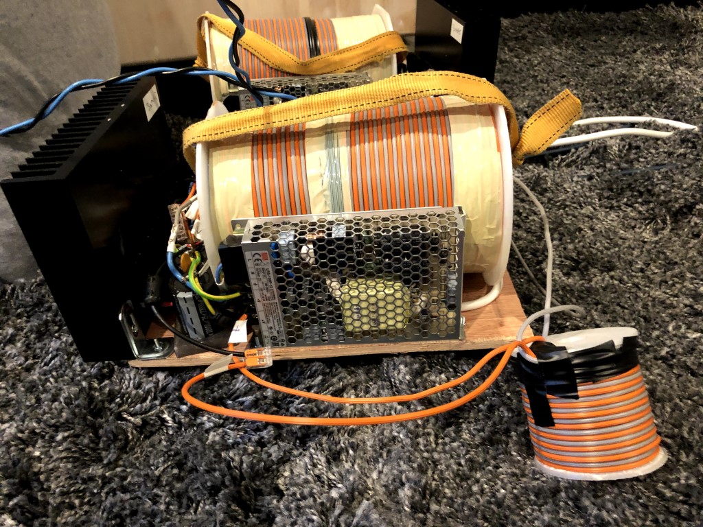
I only got two chokes this far, hopefully the remaining two will be ready this evening.
Then I'll listen.
I only got two chokes this far, hopefully the remaining two will be ready this evening.
Then I'll listen.
Got the remaining chokes ready and mounted. Did a quick listening and thought something wasn't right.
Then I realized that the bias must have changed when I added the chokes as the voltage drops half a volt or so at both ends.
So I re-trimmed the bias but now at a input level for 4 W out.
And I found out that the span for the bias is quite small - only a couple of hundred millivolts.
I also found that the bias is individual for each SLAPS.
Still got some listening to do though.
Try a microwave oven transformer. I use them on my 50w SE Class A amp. They handle 10A are about 67mH and 0.5ohm DCR. Air gapped steel plates. About $30ea on eBay.
For example (look for MD-803-AMR):
WestBend EM925AJW-P1 Microwave Transformer MD-803AMR-1 OBJY2 E306927 WMD-R | eBay
I have 6 of these and they sound superb.
For example (look for MD-803-AMR):
WestBend EM925AJW-P1 Microwave Transformer MD-803AMR-1 OBJY2 E306927 WMD-R | eBay
I have 6 of these and they sound superb.
Try a microwave oven transformer. I use them on my 50w SE Class A amp. They handle 10A are about 67mH and 0.5ohm DCR. Air gapped steel plates. About $30ea on eBay.
For example (look for MD-803-AMR):
WestBend EM925AJW-P1 Microwave Transformer MD-803AMR-1 OBJY2 E306927 WMD-R | eBay
I have 6 of these and they sound superb.
I'm sure it's a good idea.
But to add a $30 choke to a $20 SMPS seems a little bit costly to me.
Hi solhaga,
Its easy to understand your enthusiasm for the giant bifilar air-core coil in the Source and Drain legs since it directly affects the sound quality. But for the hash on the SMPS-supplied rails, wouldn't a much smaller pot core, or toroid, or even a simple coil wound on a ferrite or iron powder slug be just as effective? and have lower DCR and be a lot less susceptible to external and internal EM fields?
There's no need to be concerned about supply noise to the op amps -- they have many 10's of dB of PSRR at any frequency of interest, whereas your output stage has practically none.
However the op amp bypassing needs adjustment. Earlier you mentioned that you had 100 nF rail-to-rail, but not including ground. Instead (or in addition to), each rail should have its own cap to ground, both for stability and to provide the current it'll need to drive the highly capacitive MOSFET Gate.
What a fun, interesting project.
Best Regards,
Rick
Last edited:
Hi solhaga,
Its easy to understand your enthusiasm for the giant bifilar air-core coil in the Source and Drain legs since it directly affects the sound quality. But for the hash on the SMPS-supplied rails, wouldn't a much smaller pot core, or toroid, or even a simple coil wound on a ferrite or iron powder slug be just as effective? and have lower DCR and be a lot less susceptible to external and internal EM fields?
There's no need to be concerned about supply noise to the op amps -- they have many 10's of dB of PSRR at any frequency of interest, whereas your output stage has practically none.
I had already tried that, didn't help.
Well, there are opinions here. Maybe I misinterpreted this one.Hi solhaga,
However the op amp bypassing needs adjustment. Earlier you mentioned that you had 100 nF rail-to-rail, but not including ground. Instead (or in addition to), each rail should have its own cap to ground, both for stability and to provide the current it'll need to drive the highly capacitive MOSFET Gate.
Hi solhaga,
What a fun, interesting project.
Best Regards,
Rick
Thank you.
I saw that the inductance increased with a iron core when I worked with SLAPS for bass, and that the low frequency response improved.
So before I put this SLAPS into a box, I had to measure how it performs with an iron core in the SLAPS coil.
I had already increased the DC block's capacitance to 39000 uF.
Upper curves are without iron core, the lower with:
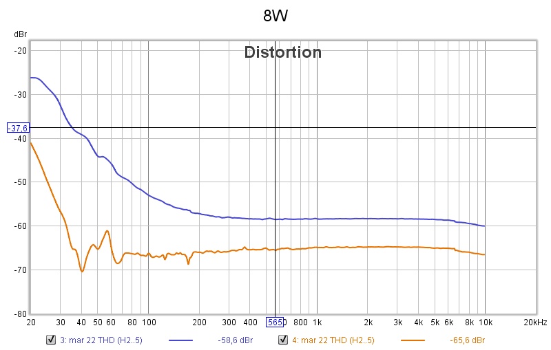
8 W:
4 W:
1 W:
There was no surprise that the distortion was lower and frequency response better in the low frequency end,
but that the overall distortion level was reduced by 7 dB was.
With these distortion levels and this frequency response this amplifier could, with the support of a sub amp, alone power a high sensitivity full range speaker.
Apart from the VAS stage (OP amp or tubes or ..), there is no negative feed back loop, just SLAPS!
Talk about letting the music free!
So now I have to rewind the coils for the four SLAPS for SLAM!
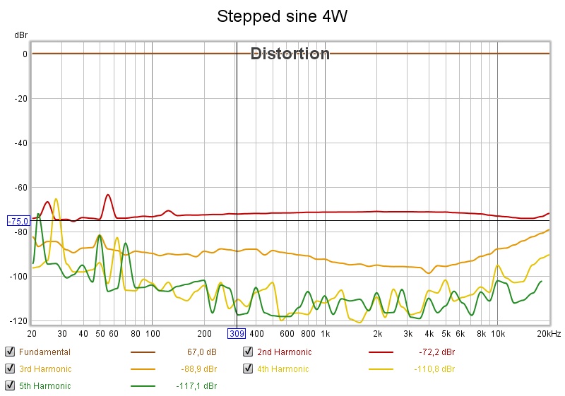
By the way, here's a stepped sine at 8 W with the iron core:
So before I put this SLAPS into a box, I had to measure how it performs with an iron core in the SLAPS coil.
I had already increased the DC block's capacitance to 39000 uF.
Upper curves are without iron core, the lower with:
8 W:
An externally hosted image should be here but it was not working when we last tested it.
4 W:
An externally hosted image should be here but it was not working when we last tested it.
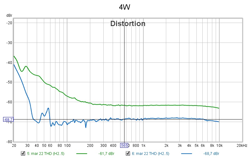
1 W:
An externally hosted image should be here but it was not working when we last tested it.
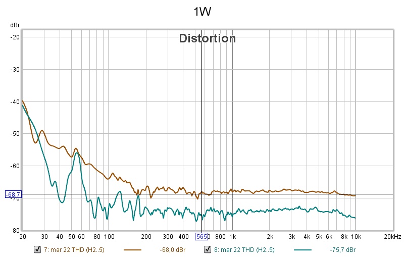
There was no surprise that the distortion was lower and frequency response better in the low frequency end,
but that the overall distortion level was reduced by 7 dB was.
With these distortion levels and this frequency response this amplifier could, with the support of a sub amp, alone power a high sensitivity full range speaker.
Apart from the VAS stage (OP amp or tubes or ..), there is no negative feed back loop, just SLAPS!
Talk about letting the music free!
So now I have to rewind the coils for the four SLAPS for SLAM!
By the way, here's a stepped sine at 8 W with the iron core:
An externally hosted image should be here but it was not working when we last tested it.
Really nice curves .. and a lot of hard work you've put into this!
Glad to see you're still working on it.
Hey, wouldn't this topology make a really fine tweeter amp -- especially for driving an unconscionably low-impedance ribbon or such?
Cheers
Glad to see you're still working on it.
Hey, wouldn't this topology make a really fine tweeter amp -- especially for driving an unconscionably low-impedance ribbon or such?
Cheers
Really nice curves .. and a lot of hard work you've put into this!
Glad to see you're still working on it.
Cheers
Thank you Rick.
Hey, wouldn't this topology make a really fine tweeter amp -- especially for driving an unconscionably low-impedance ribbon or such?
I would guess so, I haven't got the skills (yet) to calculate/measure the output impedance.

It is surely not just to divide RDSon (0.020 ohms) by three.
So with a 8 ohm load I get 2.810 Vrms and with no load I get 2.883 Vrms.
Is the output impedance then 0.21 ohm?
According to this it is that simple.
Is the output impedance then 0.21 ohm?
According to this it is that simple.
A 7 dB drop of distortion across the audioband is impressive, and a testament to the inherent power of Feed Forward Error Correction. The increased induction and coupling of the windings within the coil increases the Feed Forward Error Correction greatly.
The measured output impedance seems reasonably right when comparing with simulation.
Thanks for all the experimentation and your continuing posting of results.
These amps seems to shape up to be quite something. I hope I can visit you soon again and have a listen!
The measured output impedance seems reasonably right when comparing with simulation.
Thanks for all the experimentation and your continuing posting of results.
These amps seems to shape up to be quite something. I hope I can visit you soon again and have a listen!
A 7 dB drop of distortion across the audioband is impressive, and a testament to the inherent power of Feed Forward Error Correction. The increased induction and coupling of the windings within the coil increases the Feed Forward Error Correction greatly.
Yes, and then I haven't even started with optimization like matching the MOSFETs better.
The measured output impedance seems reasonably right when comparing with simulation.
Great! So how low can I reasonably go when it comes to drive a low impedance ribbon for example?
Thanks for all the experimentation and your continuing posting of results.
You're the inspiration! I'm just a henchman.
These amps seems to shape up to be quite something. I hope I can visit you soon again and have a listen!
Yes, perhaps the end of Corona curfew and me having finished all 10 of them will coincide.
- Home
- Amplifiers
- Solid State
- SLAPS for SLAM!