I also now get how why an input voltage that would have resulted in a lower voltage than the Vgs actually doesn't.

The difference between Vgate (dark blue) and Vsource (green) is always above Vgs in this simulation.
Should I increase Vin then there's clipping.
The difference between Vgate (dark blue) and Vsource (green) is always above Vgs in this simulation.
Should I increase Vin then there's clipping.
Attachments

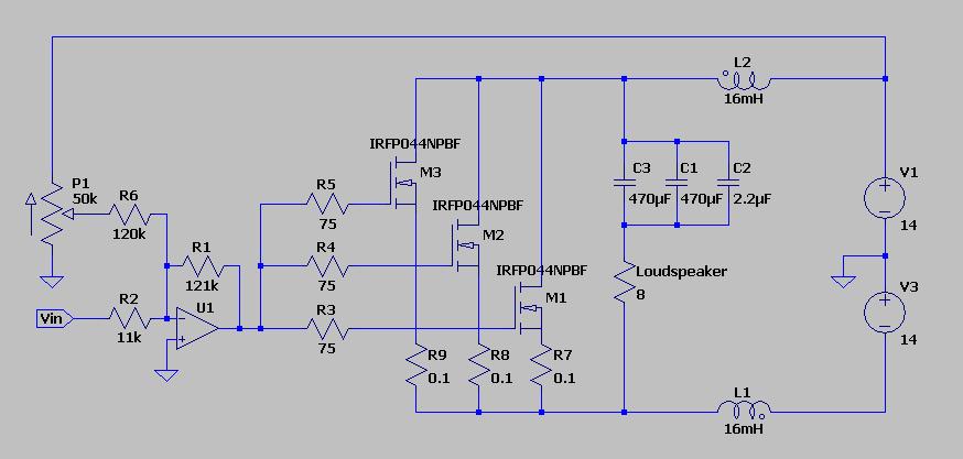
My first try on having a DC coupled input is to let the bias voltage be included in the preamplifier opamp as one of two inputs to the summer opamp.
The other input being the signal of course.
So the input capacitor is not needed and the output of the op amp can in principle be connected directly to the gate.
Any thoughts on this?
What will that affect the multiple input capacitance in the case of multiple MOSFET:s?
Any thoughts on this?
What will that affect the multiple input capacitance in the case of multiple MOSFET:s?
If the bias is stable and you don't burn your FET or power supply by plugging in or out the signal cable to the OP-amp, then I think it is a great idea. I don't like coupling capacitors in the signal path, and I avoid them when I can.
Cascoding will lower the gate capacitance seen by the OP-amp. You can always use a more powerful OP-amp or a source follower coupled P-channel MOSFET to drive the bank of multiple parallel MOSFETs.
Great! Then I will purse with the op amp summer.
But I guess that I still need a gate resistor?
I can always simulate multiple gates capacitance by connecting capacitors to the one MOSFET amplifier in order to see if the op amp's driver stage is enough.
But I guess that I still need a gate resistor?
I can always simulate multiple gates capacitance by connecting capacitors to the one MOSFET amplifier in order to see if the op amp's driver stage is enough.
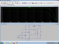
Seems fast enough. Here simulated with an IRF9640.
Great, then I'll know the target for the additional capacitor addition.
I still need a gate resistor?
Yes! MOSFETs are prone to rf-oscillations if the gate is directly coupled to the world outside of the device. They need some small gate capacitance.
The difference being that a fixed capacitor has a given value but the gate of a MOSFET is very nonlinear. The gate capacitance is highly variable dependent on the voltages and currents trough the device.

The gate capacitance of an IRFP7430.
Aha, but for a given Vds I can then actually simulate with external capacitors.
But then again, why bother - better to actually measure with the multiple MOSFETs in place.
But then again, why bother - better to actually measure with the multiple MOSFETs in place.
Simulation vs reality
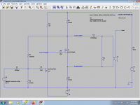
This is how the single IRFP054 simulate with an input voltage that brings the amplifier to the verge of clipping.
The DC GDS voltages are marked, both the simulated and the real.
Vpp is about 35 V, so that would mean a output power of about 19 W.
THD is rather high though.
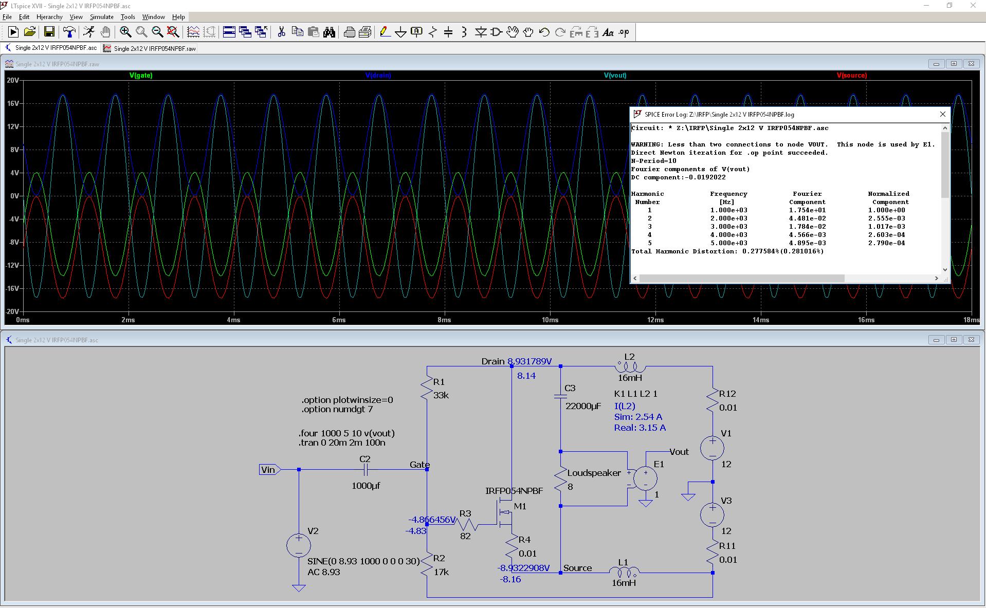
In the real amplifier, I get clipping at an output voltage of 23 Vpp.
That is an output power of 8.3 W.
But that is due to that the pre-amplifier clips the input signal at -12 VDC as it is asymmetric around the bias at -4.83 V.
Increasing the input level even further, I get clipping at the positive at 32 Vpp output.
So it is a trade off, I can get as much as 16 W if I scrap the idea of having the bias via the op amp summer but then I need the input capacitor.
On the other hand, do I really need 16 W at a probably rather high distortion level?
Anyway, I'd say reality verifies the simulation.
This is how the single IRFP054 simulate with an input voltage that brings the amplifier to the verge of clipping.
The DC GDS voltages are marked, both the simulated and the real.
Vpp is about 35 V, so that would mean a output power of about 19 W.
THD is rather high though.
In the real amplifier, I get clipping at an output voltage of 23 Vpp.
That is an output power of 8.3 W.
But that is due to that the pre-amplifier clips the input signal at -12 VDC as it is asymmetric around the bias at -4.83 V.
Increasing the input level even further, I get clipping at the positive at 32 Vpp output.
So it is a trade off, I can get as much as 16 W if I scrap the idea of having the bias via the op amp summer but then I need the input capacitor.
On the other hand, do I really need 16 W at a probably rather high distortion level?
Anyway, I'd say reality verifies the simulation.
Attachments
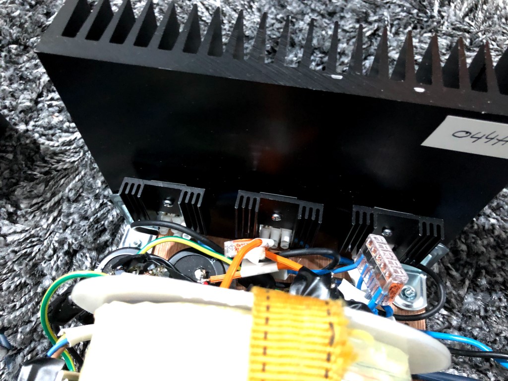
Heat sink
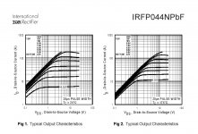
I've decided to go for IRFP044, it shows a couple of dBs lower distortion comparod to the IRFP054 in this circuit.
From the data sheet I get Tjmax 175 C and Rjunction to case 1.3 C/W.
The heat sink has a thermal resistance of 0.53 C/W
The heat pad has 0.4 C/W I get:
Qm = (175 - 30)/(1.3 + 0.4 + 0.53) = 65 W
An Id of 4 A and a Vds of 14.4 V (2 x 12 V DC - Voltage drop in the coils: 2 x 4 A x 1.2 ohm) given a power dissipation Pd of 57.6 W.
So I say that the heat sink is barely sufficient, but please correct me if I'm wrong.
So what about the linear derating? From the data sheet it is 0.77 W/C and Pmax is 120 W
The heat sink gets about 50 C.
So maximum power is 120 - 0.77x50 = 81.5 W.
Is that correct way of calculating? Again, please correct me if I'm wrong.
I've have also put a smaller heat sink on the plastic top of the MOSFET, it gets a lot hotter; around 75 C.
Is it needed or is it actually for worse?
Last edited:
Your math is probably right, but it is a bit optimistic according to my experience.
I would not run more power through the mosfet then 30 watts of continuous dissipation for any prolonged period of time. It might take more power but it is pushing the luck a bit. If you have enough spares and don´t mind swapping out the device from time to time then you can probably run 50 watts of continuous dissipation or so.
The transconductance seems to decrease at 175 degrees C compared to 25 watts. The transfer curves does not show the area around the operating point of the device in your amp, but the general trend seems to indicate lower transconductance at very high temperatures.
If you really want to run 4 amperes of continuous current then you should parallel 2 or 3 devices with a small source resistor on each device.
Attachments
Thanks.
My first thought is to actually push my luck, but I think that I'll reconsider.
It'll be a small effort to make it two or three MOSFETs per SLAPS.
Lets see how the matching of the IRFP044 goes, how close do they need to be?
Depending on the outcome of the matching, I'll decide if there will be two or three MOSFETs per SLAPS.
how close do they need to be?
As close as possible to use the smallest possible source resistor. A source resistor will somewhat flatten the quadratic character of the mosfet and lower its effectiv transconductance. They usually sound better (but not always measure better) with less source resistance. Can you get a few devices with only a few mV difference for a given current with only 0,1 ohm source resistance per device, being thermally stable when bolted to the heat sink then you should be happy.
Great.
As IRFP044 has lower gate capacitance, almost a third of the IRFP054, it is a better candidate for a pure parallel SLAPS installment.
I won't need the smaller heat sinks, so the large heat sink will not be that crowded.
As IRFP044 has lower gate capacitance, almost a third of the IRFP054, it is a better candidate for a pure parallel SLAPS installment.
I won't need the smaller heat sinks, so the large heat sink will not be that crowded.
Last edited:
As close as possible to use the smallest possible source resistor. A source resistor will somewhat flatten the quadratic character of the mosfet and lower its effectiv transconductance. They usually sound better (but not always measure better) with less source resistance. Can you get a few devices with only a few mV difference for a given current with only 0,1 ohm source resistance per device, being thermally stable when bolted to the heat sink then you should be happy.
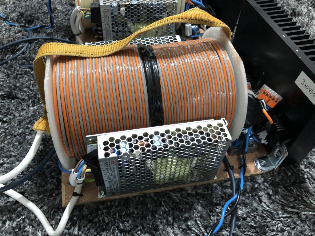
I used your method above to match the MOSFETs, I call the measured voltage Vm below.
Here's a couple of actual examples with matching MOSFETs for the first two SLAPS: 3x044A and 3x044B.
For 3x044A, with matched MOSFETs with Vm 3.750, 3.751 and 3.754, I didn't manage to get a balance between the currents through the resistors.
The MOSFET with the lowest Vm proved to draw a lot more current.
I even switched it to a MOSFET with Vm of 3.767, but I got the same imbalance.
The matched MOSFETs for 3x044B, had Vm 3.688, 3.690 and 3.696.
The voltage over the 0.1 ohm resistor measured respectively 162, 163 and 152,0 mV (after 30 minutes).
Within the 5 % tolerance of the resistors that is.
So I guess I got lucky with this one.
I will rematch the MOSFETs for 3x044A, perhaps I did a sloppy job; not waiting an equal amount of time before measuring Vm or something else.
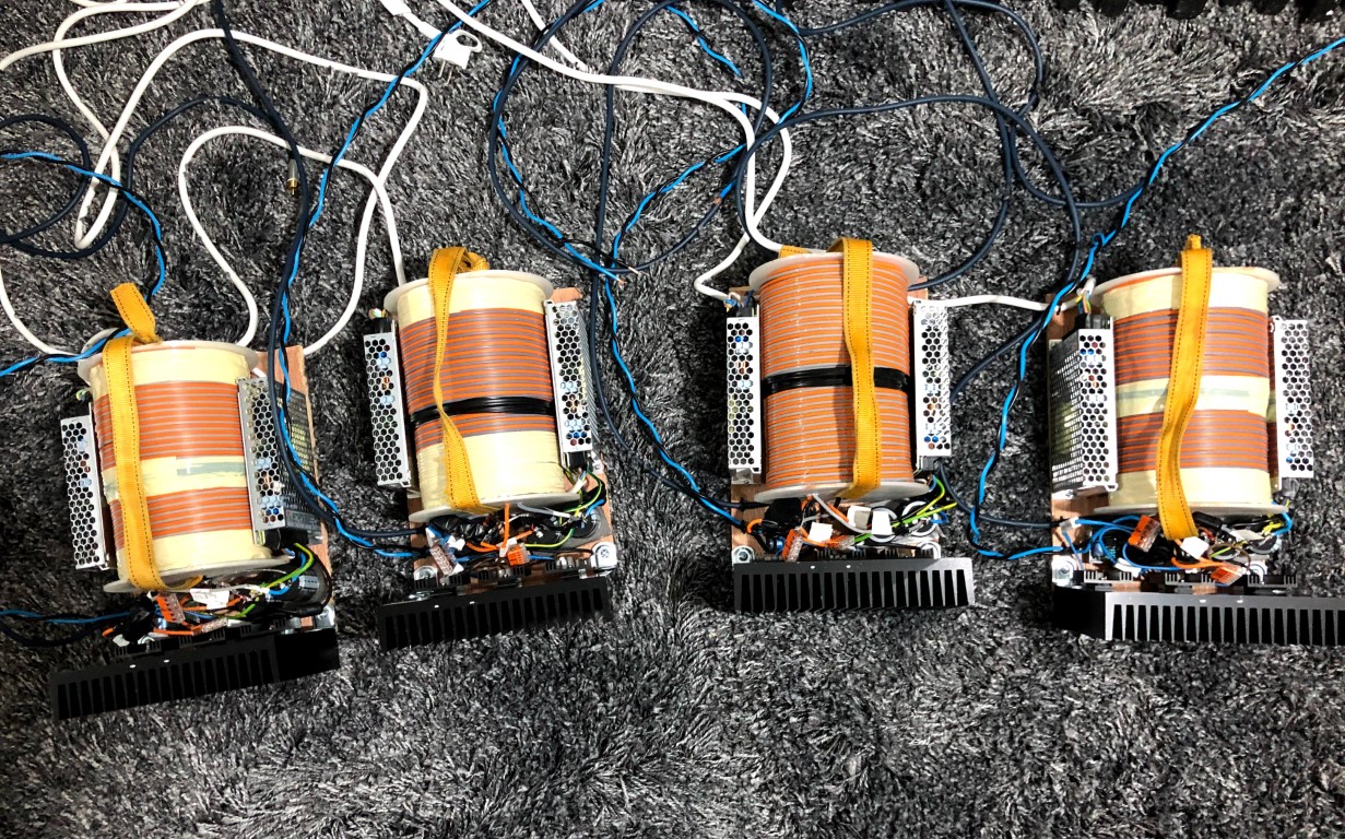
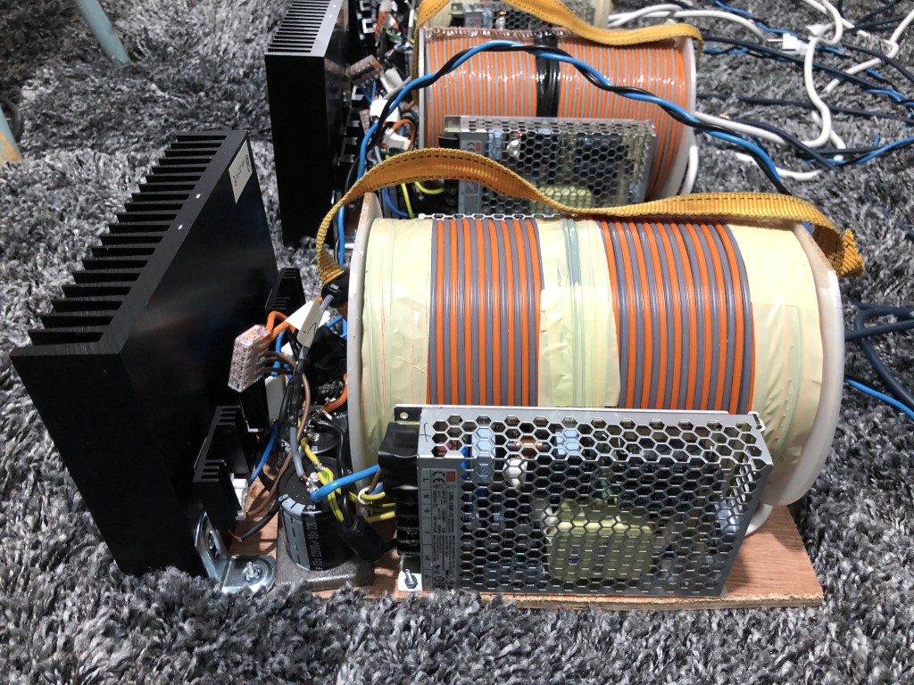
This is what I've built:
Just lowered the gain a little bit and the gate voltage has no gain at all so the trimming is more accurate
Finally matched four triplets and the first four SLAPS are built:
An externally hosted image should be here but it was not working when we last tested it.
Just lowered the gain a little bit and the gate voltage has no gain at all so the trimming is more accurate
Finally matched four triplets and the first four SLAPS are built:
Very nice build!!!! 🙂 
I saw your short "review" at hififorum.nu, and I am glad they delivered what I said they would. I hope I can visit you to listen to them driving your AMTs soon. I have only heard single channel setups with a few different Mosfets, so I am curious how four channels with great DACs, great processing (xover etc) and your great AMTs will sound.
Is the slight harshness we heard at high spl and complex signals gone?
Regards,
Johannes
Yes, I just need to make a perforated cover.Very nice build!!!! 🙂
The build is quite serviceable, just loosen two nuts and the heat sink with the MOSFETs will come off if I want to replace them.
For instance swap the 044s with 054s. I have more of them than the 044s, so I might get a closer match.
Perhaps they will sound different as well.
Any time at all. I'm really curious what you will think.I saw your short "review" at hififorum.nu, and I am glad they delivered what I said they would. I hope I can visit you to listen to them driving your AMTs soon. I have only heard single channel setups with a few different Mosfets, so I am curious how four channels with great DACs, great processing (xover etc) and your great AMTs will sound.
Yes, I would say so. There are even information/music that were masked by the harshness.Is the slight harshness we heard at high spl and complex signals gone?
Next step, apart from listening of course, is to do some measurements.
Even swap the terminals to see what happens with the second order distortion; is there really a measurable pre-distortion effect?
is there really a measurable pre-distortion effect?
"Triodity" to cancel loudspeaker distortion
Here are actual measurements of the pre-distortion effects on a loudspeaker. Nelson Pass seems to approve of my experiments (which are based on his great articles from First Watt).
I test several different devices and several different operating conditions.
- Home
- Amplifiers
- Solid State
- SLAPS for SLAM!