Thinking about making a 28b clone full bridge, and wanting only ssr muting on the output(s), I've been pondering about the best way to make mosfet ssrs control via optocouplers only, and of course, on both sides of the speaker.
I'm not at all an expert on mosfets and I was wondering if anyone has done anything with such mosfet ssrs, so I'm not trying to reinvent the wheel...
Anyone?
I'm not at all an expert on mosfets and I was wondering if anyone has done anything with such mosfet ssrs, so I'm not trying to reinvent the wheel...
Anyone?
I forgot to mention, the most important thing is it has to be with non SMT type parts.
I was trying to find an equivalent optocoupler to the vishay vom1271, and I'm still digging.
It's an SMD and I'd like the same thing in through hole. That would make it easy to command those mosfets from remote and from micro-controller signals.
I want to have ssrs on the rails plus both sides of the speaker outputs...
The bryston 28b has electromechanical muting, but it mutes from within the amp itself, which works nicely and doesn't introduce anything into the signal, as when the relay isn't activated, the contacts are open and nothing comes into the amp from that.
They don't have anything on rails, and nothing on the amp's output either.
Spookydd if you look back earlier in this thread to post #23 you'll see that I built a couple of mosfet loudspeaker protection relays on a piece of perfboard so that they have the same pin spacing and configuration as a standard mechanical relay. I used an ASSR-V621-302E photovoltaic optocoupler. This is nominally smt but its really an 8 pin dip package with the pins shortened and bent a bit - straighten the pins and you have a through hole part.
You might find this article of interest A DC Fault Protection Circuit for Audio Amplifiers
I looked again at that stuff about the ssr on perfboard. I had not retained the part about being smt, because when it is, I always look for through hole alternatives.
I found a datasheet for that pv opto and apparently it does also exist in through hole pdip8, which I checked on mouser and found that:
ASSR-V621-002E Broadcom / Avago | Mouser France
It is a little pricey...
But I was digging for such alternatives and had also found that one:
APV1122 Panasonic Industrial Devices | Mouser France
Seems it needs less ooomph to command and is a tiny bit cheaper. It does have only one output though, so no possibility of combining...
I would like spice models to try some things out... Found a couple of models for the mosfets fdp083n15a, which I'm considering for the rails, and the fdh055n15a, which I'm considering possibly for the speaker output(s). It seems a little sturdier and has lower RdsOn, which is appreciable especially for use on a bridge, because there would be 2 ssrs added, one on each leg, so the lower the RdsOn is, the better. This stuff removes some damping factor from the amp... But hopefully it's low enough when compared to other things like cables and plugs...
My goal being to have the amps in a rack located right next to the speakers and with the shortest cables possible, makes the cables a bit less of a concern for their resistance.
One goal also being to make each power amp as a module and trying to avoid multiple pcbs and wiring kept to a bare minimum, I already know it's going to be a challenge to layout a pcb with that much stuff on it, like the huge cap banks and a shitload of output devices...
The only wiring that is unavoidable, are the leads from the toroid and the few for the housekeeping (softstart, mute, etc...)
Will be challenging, and a big/heavy module, and I want to try to make it the best possible.
The actual bryston 28B is such a huge and heavy beast, with their beefy heatsinks, humongous toroid and big case, it's going to be hard to squeeze that into a smaller footprint...
I was just wondering about something, about the ssr command signal.
If the command signal comes from an other pcb that is physically located a little away from the amp module, the signal wires to the ssr optocouplers would have a bit of length, and I'm wondering if there are reasons to worry about that length, with small losses, which might not be much, but maybe some potential interference if they pass not far enough away from toroids and perhaps mains cabling.
So I'm wondering which type of cabling would be best:
- simple 2 wires twisted pairs, one being a gnd
- shielded 2 wires, with both shield and a wire being gnd
Length of wiring such things in a rack with multiple power amp modules, a xover, plus a pcb with all mains stuff with a central microcontroller to handle it all, might not exceed much a length in the order of 50-60cm or so, but the routing of those wires might have to go around some big toroids and pass near some mains power cabling supplying those toroids.
There could be some EMI or switching pulses from all that stuff, especially at power up, which is also exactly when the command signals are needed most for the ssrs and other things...
Things to ponder...
The bryston clones seem like among the best amps we can build, and I'm thinking about having all 4 ways/amps in the rack to be such amps. The channel for the highs will not need to be anywhere near as beefy as the low end one, but it needs to handle the highs as good as possible, so although the 2 lowest channels would be heavy duty with mjl2119x outputs, I think the 2 upper channels should use the faster mjl4281/4302 types. Maybe a clone of the 4B might be appropriate, with the fastest devices available.
Realizing that the fdp083n15a mosfet won't cut it for the 28b bridge with its "only" 150V, I looked for more with at least 200V breakdown, and found this one that seems like a good potential candidate:
IRF200P222
IRF200P222 Infineon Technologies | Mouser France
Should be enough for the +/-~92-93V rails and amp output, and they have even lower RdsOn. I would parallel 2 to cut that RdsOn in half, which would also double the current handling capacity.
The question is: can it be triggered properly from one of those optocouplers as we just discussed? And fast enough.
Those have max 6.6mohms RdsOn, which with 2 paralleled is cut in half, but we're back at that much because 2 sets are used for a bridge anyway..
I was also wondering about one other thing: with the ssr aimed at the speaker output, since there are 2 mosfets in series, doesn't this add their RdsOn? They don't conduct together at the same time depending on the signal's polarity passing through them, so one of them is passing while the other isn't, and the signal blocked by the non-passing one goes through the bypass reversed diode, so how much resistance do those diodes bring in?
Hi..everyone.... please give me your summary of experience for following questions
(1)what are the changes need to use 90v power input in 4b sst
(2)most suitable replacement for PN100,200
Thanks
Your questions have all been covered in previous posts
I'm pretty close to having a 28b bridge clone simulation to work. However I'm having an issue that I haven't been able to solve yet.
I made an improved version of the power amp part, with much less distortion and works nicely, which when used in a full bridge config with the original DOA68 as is, works very well.
However, I made an improved DOA68, which works extremely nicely on its own, but when 2 of them are coupled together as with the original DOA68 to get the 2 opposed signals to drive the amps, that improved DOA68 oscillates, only when both are connected to the input signal. They do work quite fine independently, if they're not both connected to the input signal.
Very weird and I have yet to find what the problem is.
Once I get this solved, I'll have the base to start a pcb layout for a cloned 28B "improved".
For info, the improvements that worked for the DOA68, that actually improved performance, besides adding current sources on the ltps, are cfp for the ltp, current mirrors with the helper tranny plus that Cordell suggested extra res to make it work reliably. Other than that, only value adjustments were made to make it work properly.
The improvement done on thd is pretty big, with less than .2ppm left at 20khz on a 1k5 load, gain of 2 (6db) and 12Vpeak output signal. Plenty to drive the power amps fully.
I only need to solve that issue with that oscillation when both DOAs are connected at the same time to the input signal...
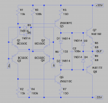
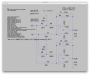
To illustrate, here are the 2 versions of the DOA and a quick test rig to check that out individually.
This tests only one at a time, and I have an other rig to test 2 of them, and that's where trouble starts.
I'll post something later about that as well..
I've tried various possible improvements, and although many do work fine, most don't bring any real improvements, nothing that warrants using them. And actually some improvements aren't improvements at all and actually make it worse.
I thought using led based current sources wouldn't change things too much, not really improving thd performance but would provide a more thermally stable concept, but it turns out this makes thd worse, so not so good for the DOA. Works fine for the power amp's input stage though, go figure!
Cascoding the ltp is worse, either with or without current mirror loads, so that's out.
Enhanced vas doesn't help. It doesn't make it worse, just brings nothing except increasing the part count.
I even tried doubling the outputs, but that too only increases part count without bringing real improvement.
An extra FET current source between the current source tails also makes it worse instead of improving, and curiously this works better on the power amp's input stage as well. Puzzling...
Attachments
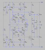
Here is the test rig used to test 2 DOA sub-circuits together.
This works perfectly if the DOA is the plain original DOA68, which uses 20k/40k resistors to set the gains, and the compensation cap on the feedback is 22p instead of 3p9.
The thd with that gain set up of 2 (6db) and a 6V input signal at 20khz, the load resistors 1k5 for all configs, is a little over 4ppm on one output, and the 2 signals are properly in opposition.
But when using that improved DOA68, with the cfp/degen/mirrors and all that, with the comp cap on feedback of 3p9, oscillations are present when both are connected to the input signal. That stops when either one is used and the other disabled/disconnected from the input.
And this happens no matter which resistance values are used to set the gain, always for a gain of 2.
A mystery I haven't been able to solve yet. Increasing the compensation cap value doesn't help stopping this.
If anyone has any suggestions, I'm all ears.
Attachments
Omit R2 and R8?
Can't work that way. Those are opamps after all, they do need their resistors to set their gain.
It works fine with the original DOA, and that's how they use it too.
Bit of mental arithmetic gives me a vas current of about 2.5mA and an output stage of 10mA - about right?
On the improved DOA, that's about right, more or less. In the ballpark.
It's closer to 2.7mA tail currents, and not too far from 15mA in the outputs.
Could also try adding a third module to make a classic instrumentation amp. Haven't figured it out yet but I have a sense that you've got cross coupling which leads to positive feedback with the new higher olg module.
But how would you explain it does work right with the original DOA?
It's how it's used in the actual amps, except they insert in 3k48 in the DOA's positive input. I removed it in the test rig, but it makes no difference with or without, with the original working fine and the improved goes into systematic oscillation. The improved DOA works great on its own.
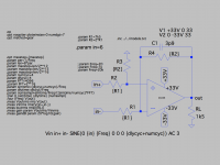
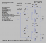
Here is a test rig that has the 3k48 resistor in the DOA's positive input, as they have it in their amps.
This is using the original DOA, as posted earlier as a sub-circuit.
And this is using the same res values as used in their amps, the 20K and 2 x 20K to set gain, plus that 3k48, for which I would really like to know what its use is...
It does work the same without that 3k48 res anyway. No oscillations or whatever.
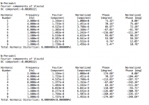
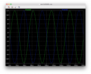
I load the DOA's the same, with 1k5, give them the same input signal of 6V (peak) and the res ratios give the 2x gain (6db). Those plots are at 20khz.
The improved DOA under those conditions, individually, has less than .2ppm thd.
This is using the original DOA, as posted earlier as a sub-circuit.
And this is using the same res values as used in their amps, the 20K and 2 x 20K to set gain, plus that 3k48, for which I would really like to know what its use is...
It does work the same without that 3k48 res anyway. No oscillations or whatever.
I load the DOA's the same, with 1k5, give them the same input signal of 6V (peak) and the res ratios give the 2x gain (6db). Those plots are at 20khz.
The improved DOA under those conditions, individually, has less than .2ppm thd.
Attachments
- Home
- Amplifiers
- Solid State
- Bryston 4B SST clone