Do you think this noise is critical?
Well, there is still audible noise, so yes, if that VReg ripple+noise is the cause.
Another thing: Do you know what this buffer stages 1+2 are for? It seems only for inverted line (when using XLR), RCA seems to go directly to into voltage amp stage 1.
Buffer stage has it's own bias poti, I accidently changed it, and don't know how to set it back, and if it matters.
BR
Last edited:
As far as I know, a soft start is needed to safely start the amplifier, so as not to damage the speakers, we can say this soft start replaces the relay, but I'm not sure, maybe Hans knows?Well, there is still audible noise, so yes, if that VReg ripple+noise is the cause.
Another thing: Do you know what this buffer stages 1+2 are for? It seems only for inverted line (when using XLR), RCA seems to go directly to into voltage amp stage 1.
Buffer stage has it's own bias poti, I accidently changed it, and don't know how to set it back, and if it matters.
BR
How did you change it? So your amplifier turns on immediately without a soft start?
Glad that noise was reduced.
A regulated supply should produce a nice and clean supply.
But when measuring it comes critical where to connect the probe.
Best is to use the large alu strip that connects the 4 big blue caps for the probe's gnd connection, is this what you did ?
Further you mentioned P1 and P6, but that probably was meant to be P1 and P4, true ?
The scope pictures 2 and 3 are almost as if it is a stable oscillation.
Did you try to trigger on the signal around 100 Khz ?
Scope pictures 1 and 4 are more like random noise, but a bit high to my taste.
About the buffer for the negative input. This was what ML changed for all their .5 versions.
Before it was a nice and simple diamond buffer. No idea why they made it so complex, a simple opamp could have done the same job.
The pot is to adjust it's DC output voltage to zero. You can measure this on P11.
Hans
As far as I know, a soft start is needed to safely start the amplifier, so as not to damage the speakers, we can say this soft start replaces the relay, but I'm not sure, maybe Hans knows?
How did you change it? So your amplifier turns on immediately without a soft start?
This can be seen as a sort of solid state relay.
It reduces the bias current to almost zero and prevents the LS output from supplying current to a speaker.
Then it releases nice and slow unlike a relay which would have caused a plop in the speaker.
Hans
No not workink for ML ot Harman.
I have a 26.5 that used teflon boards, and teflon is like chewing gum it expands when getting hot and shrinks when cooling down.
So it was an accident waiting to happen until traces got hair cracks and components became isolated.
Every two or three years my amp had to be repaired by ML for big bucks.
At that time there was absolutely no technical info available, so I took everything apart and did the reverse engineering, so I could do the repair myself from thereon.
That gave me most of my ML knowledge.
But being fed up by this constant repair, I finaly made a new modern design with smd components, thereby only using the existing transistors on the heatsinks, but the rest is completely different.
The big advantage of the ML26 is that all boards are scocketed and that there is no cabling to connect things.
So my new amp board could simply replace the old board.
Later on I dicovered that the 23.5 and the 27.5 are all based on the same concepts with almost identical components but scaled down.
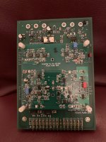
Here is a picture of the board that I designed for my ML26.
I offered it to ML, but they did not even react.
Hans
I have a 26.5 that used teflon boards, and teflon is like chewing gum it expands when getting hot and shrinks when cooling down.
So it was an accident waiting to happen until traces got hair cracks and components became isolated.
Every two or three years my amp had to be repaired by ML for big bucks.
At that time there was absolutely no technical info available, so I took everything apart and did the reverse engineering, so I could do the repair myself from thereon.
That gave me most of my ML knowledge.
But being fed up by this constant repair, I finaly made a new modern design with smd components, thereby only using the existing transistors on the heatsinks, but the rest is completely different.
The big advantage of the ML26 is that all boards are scocketed and that there is no cabling to connect things.
So my new amp board could simply replace the old board.
Later on I dicovered that the 23.5 and the 27.5 are all based on the same concepts with almost identical components but scaled down.
Here is a picture of the board that I designed for my ML26.
I offered it to ML, but they did not even react.
Hans
Attachments
No not workink for ML ot Harman.
I have a 26.5 that used teflon boards, and teflon is like chewing gum it expands when getting hot and shrinks when cooling down.
So it was an accident waiting to happen until traces got hair cracks and components became isolated.
Every two or three years my amp had to be repaired by ML for big bucks.
At that time there was absolutely no technical info available, so I took everything apart and did the reverse engineering, so I could do the repair myself from thereon.
That gave me most of my ML knowledge.
But being fed up by this constant repair, I finaly made a new modern design with smd components, thereby only using the existing transistors on the heatsinks, but the rest is completely different.
The big advantage of the ML26 is that all boards are scocketed and that there is no cabling to connect things.
So my new amp board could simply replace the old board.
Later on I dicovered that the 23.5 and the 27.5 are all based on the same concepts with almost identical components but scaled down.
Here is a picture of the board that I designed for my ML26.
I offered it to ML, but they did not even react.
Hans
Very interesting! Can you show us what this Board looks like in the case(in the assembled preamp) ? I didn't know that 26 were with Teflon boards, I have textolite boards. And what do you have a 23.5 or 27.5 amp? and what do you say about the opinion that the twentieth series is considered the best sound of all the mark Levinson series? Is this fiction or true?
I just sold a preamp to a guy with about a £60 k system. He took the ML pre out and put mine in. AD797 based.
")
Good for you, congratulations. Do you know what model ML it was, old, new ?
I did the same with my ML320, fantastic looks but I replaced it with the Bruno Putzeys preamp published in Linear Audio having a better sound.
Hans
At the time the 20 series where offered to the market,ML was market leader, but more and more they lost their position at the front, leading to their bankruptcy and takeover by Harman.what do you say about the opinion that the twentieth series is considered the best sound of all the mark Levinson series? Is this fiction or true?
What they make nowadays is still very good, but they are no longer the best of the best IMO.
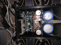
Here’s a picture of my complete amp that you asked for.
Hans
Attachments
Thanks Andrew,
That ML326S was the same as my ML320 but with Arlon boards.
Arlon was the successor of the previous less successful Teflon.
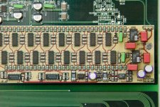
As said, fantastic looks, love at first sight but not top of the bill in sound despite the use of expensive components like four OPA627's and eight AD797's.
The main cause was probably their implementation of the Linear volume control with a zillion Fet switches, see picture below.
That's why I added a Logarithmic volume control to the BPBP with only 6 real relays instead of Fet switches , covering a 64dB range.
But let's go back to the ML27.5 because we are floating away.
Hans
That ML326S was the same as my ML320 but with Arlon boards.
Arlon was the successor of the previous less successful Teflon.
As said, fantastic looks, love at first sight but not top of the bill in sound despite the use of expensive components like four OPA627's and eight AD797's.
The main cause was probably their implementation of the Linear volume control with a zillion Fet switches, see picture below.
That's why I added a Logarithmic volume control to the BPBP with only 6 real relays instead of Fet switches , covering a 64dB range.
But let's go back to the ML27.5 because we are floating away.
Hans
Attachments
I must confess that I made a bit of a mess of the numbers, sorry for that.
Originally I bought a 20.5 that was later upgraded to the 20.6 with the teflon boards and with a new 20.6 faceplate all done by ML.
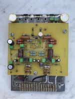
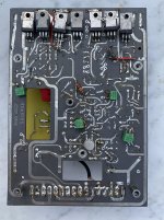
Here you see the remains of my 20.6 board, where I already had replaced the upper teflon board with discrete buffer for an OPA627 opamp buffer, but now also using the same opamp as buffer for the positive input, making it possible also discard the large 2.2uF and 10uF caps (see the large holes in the lower PCB). This all situated on an epoxy board together with the soft start circuit.
But as you know, in the end I replaced them completely by my own design.
The second picture shows the backside with heatsink removed giving a better view on the often repaired teflon board.
Hans
Originally I bought a 20.5 that was later upgraded to the 20.6 with the teflon boards and with a new 20.6 faceplate all done by ML.
Here you see the remains of my 20.6 board, where I already had replaced the upper teflon board with discrete buffer for an OPA627 opamp buffer, but now also using the same opamp as buffer for the positive input, making it possible also discard the large 2.2uF and 10uF caps (see the large holes in the lower PCB). This all situated on an epoxy board together with the soft start circuit.
But as you know, in the end I replaced them completely by my own design.
The second picture shows the backside with heatsink removed giving a better view on the often repaired teflon board.
Hans
Attachments
Glad that noise was reduced.
Once again, thanks for your help, Hans. Yes, Right channel noise reduced, much better, but still some noise in both channels. VReg +- is set exactly.
Best is to use the large alu strip that connects the 4 big blue caps for the probe's gnd connection, is this what you did ?
Further you mentioned P1 and P6, but that probably was meant to be P1 and P4, true ?
Yes, P1 and P4, of course, sorry.
I tried different grounds: P16, which is easy to reach, but also the alu strip via longer lead to probe-GND. Same result.
I don't remember how the picture was exactly triggered, I looked at 10kHz and 100KHz this morning (triggered on the spikes).
This is previous image 1. left - VReg_neg
10Khz

100kHz

The pot is to adjust it's DC output voltage to zero. You can measure this on P11.
Interesting. Ok, it's adjusted to zero.
So, I'm wondering how to proceed.
I'm a bit mystified why changing C21 did what it did.
Perhaps I'm going to change C22 as well, and the 1900uF caps (I have some used spares) and see what this does.
If no result, I might have to take apart the boards and see if I can track the noise backwards from P6, P7. E.g., shortening lines R23, R36 to ground to see what it does.
BR
Last edited:
before further responding to your posting, first a few questions:
1) what dc current with your multimeter flows from P6 to P7. This may sound a bit scarry, but don’t worry it’s completely harmless.
1) what noise do you measure with your scope at P11 with minus input shorted.
2) what noise do you measure with your scope at the LS output with both inputs shorted
3) how do the AC voltages look on both smaller blue caps triggered at your mains frequency. I would like to see on the AC scope picture how much the voltage drops between two charge cycles to be able to calculate how sound these large caps still are.
Hans
- Home
- Amplifiers
- Solid State
- Mark Levinson No.27 amplifier,,,NEED HELP