You has actually eliminated the purpose of the R9 resistor, it no longer fulfills the purpose of the HBR.
I went ahead and simulated this HBR:
Any current passing this resistor will create a voltage over the resistor, so I added an AC source over the resistor in the sim. The result is that any voltage over this resistor is amplified by the amp as any input signal, causing amplified noise at the output.
A 'true' HBR will not amplify the current/voltage over the resistor, voltage at the output will be the same as the voltage over the HBR, since feedback is grounded to the same signal ground. See attached example on VFA amp. Not as easy on CFA because of higher currents in the feedback path..
Attachments
Did you add R45/C18 & R46/C19 as in my schematic? This is what fixed it for me.
Values are not critical, just something close enough should do, I'm guessing 300-500p and 50-150ohm.
The lower value on R4 & R5 was just 'icing on the cake' to increase the current a bit, did not make much difference other than a little bit nicer square wave flanks.
Hi Rally,
Yes I had tried it but without a great deal of success (from memory I think there was a slight reduction but not complete elimination) - holding it in place over the required junctions with my hand on the original circuit.
I'm working with Bonsai on this and also doing my own sims to see if I can pick up anything untoward.
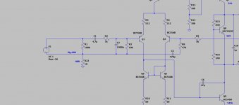
Here is some of stuff I've been working on. The model for the VAS is crude, but does demonstrate that it is possible to get the VAS to oscillate given the right conditions. Important to note that the simulation oscillations are 10x higher in frequency than that reported by some of you. however, I would need to do more work on the VAS loading (Q2 in my sims) to see if I could more accurately replicate the oscillation problem you are getting at 20 MHz.
")
Attachments
Last edited:
Thanks for all the work you've been doing Bonsai. Really appreciated.
Because some people have a problem but some don't is there any possibility this oscillation could be due to someone running a Ham radio in the vicinity (I've tried to get a better idea of the user radio frequencies in this vicinity but can find nothing definitive)
Because some people have a problem but some don't is there any possibility this oscillation could be due to someone running a Ham radio in the vicinity (I've tried to get a better idea of the user radio frequencies in this vicinity but can find nothing definitive)
Tony, the quickest way to test for this is to short the amplifier inputs. . It can come down the speaker cables as well, but you could connect headphones instead of speakers to the output to check this.
Also, be aware that often there can be HF garbage on the mains. I have one of those power line network extenders and that can generate a lot of HF crud (MHz). This stuff will blast straight across transformers, diodes and filter caps.
Also, be aware that often there can be HF garbage on the mains. I have one of those power line network extenders and that can generate a lot of HF crud (MHz). This stuff will blast straight across transformers, diodes and filter caps.
The only other thing I can suggest at this stage is to insert a 47 ohm resistor in the base of transistors Q10 and Q11. Keep the resistor as close to the transistor base as possible.
Can you confirm you are using all the same transistors as in the schematic - ie none of the substitutions suggested in the build doc.
Can you confirm you are using all the same transistors as in the schematic - ie none of the substitutions suggested in the build doc.
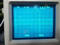
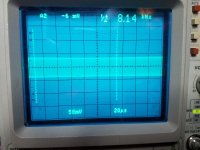
Tony can you put up some more pictures of your oscillation. Can you zoom in to show a few cycles and then zoom right out so we can see the envelope of the oscillation (so time base say 100x or 200x slower than for a few cycles across the screen).
Hi Bonsai,
Would you prefer these pics as 'single shot' from 'normal mode' or as an accumulation, around 256 average?
I have some first impressions after listening to the amp some hours for a few days now.
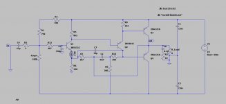
My favorite amp is a modified JLH (schematic below -comp cap), also dual mono.
Based on measurements they are pretty similar at low power, with the distortion spectrum and levels (yes, the JLH is -90dB territory with dominant 3rd too).
Speakers I'm using are DIY Troels PMS-inspired 3-way wide curved baffle, but using other (time aligned) drivers, and I put a lot of effort in the XO to make an easy load for the JLH amp. So, they are minimum 6ohm, easy phase, and decent efficiency.
I listened to a lot of different music that I know well ranging from acoustic guitar music like Tommy Emanuel, pop music like Dire Straits/Sting/Toto to hard rock like Rage against the machine.
For the low end, the KX is better in every way. Effortless and controlled bass, and of course there is more power if needed.
Mid is more difficult to differentiate. I would say mid is a little bit more detailed with the KX, and moving up to high mids/treble, there is a little more detail too. Maybe a bit against my preference, since I prefer a smooth and subtle treble. It's not harsh, just sounds a little brighter than the JLH somehow.
On the 'sound stage' it seems there is a little bit less perception of 'depth' with the KX, maybe because it sounds slightly brighter and that would make it sound more forward, I don't know.
However, no fatigue or headaches from the KX. I tend to get that with some amps that sound 'bright'.
I have tried in both high and low Iq, and cant really say I hear a difference. Probably the amp is working in class A all the time at low Iq too, since I don't play very loud, and speakers are an easy load.
Still want to do some more experimenting with it. Maybe add the mentioned resistors, play with compensation a little, and it should be built in to a chassis of course
Attachments
Last edited:
Great report, and an elegant solution to the problem! Maybe I should add those resistors to Q1&Q2 even if I don't see oscillation any more, just to be on the safe side.
Have you also measured distortion and looked at the square wave response before/after doing the mod?
Thanks.
Have not measured distortion yet, but don’t expect anything radical - perhaps even a bit better. Square wave looks clean - there is a bit of overshoot on my scope shots but that’s because the load is quite inductive/capacitive with fast rise times. I’d need to redo it with just a resistor across the output terminals to get an accurate picture.
Usually the drivers dont need base stoppers in an EF2 - definitely in an EF3 - but it may help if folks are getting these problems.
I think the additional decoupling (1uF 50 V 0805’s across all the 1000uF caps is worthwhile addition as well.
I had the amp playing last night with no probs - sounded v. Good.
Last edited:
I am using the transistors from the BOM and the ripple eater. Neither have any mods done yet.
FYI - Early on in this investigation should had suggested trying an RC between the 0V and Zobel connections on the amp board. Holding an RC on the quick disconnects caused the oscillation to go away completely. I know we are past that now but thought that it might still be useful info.
FYI - Early on in this investigation should had suggested trying an RC between the 0V and Zobel connections on the amp board. Holding an RC on the quick disconnects caused the oscillation to go away completely. I know we are past that now but thought that it might still be useful info.
Can you link the ripple eater pass transistors out - that's the 15032 and the 15033 devices. The PCB is marked with the transistor BCE connections.
I've just been trying to eliminate all other possible causes.
(NB I blew my ripple eater up a few months ago when I drove the amp at full power continuous into 2 Ohms - that's pushing about 100W RMS on my amp. The ripple eater is of course a big EF.)
I've just been trying to eliminate all other possible causes.
(NB I blew my ripple eater up a few months ago when I drove the amp at full power continuous into 2 Ohms - that's pushing about 100W RMS on my amp. The ripple eater is of course a big EF.)
I forgot to mention, and change in my schematics, I'm running lower gain, so R25 is 33ohm in my amp. Not that I think it should matter?
I also want to try some mica-caps for compensation instead of NPO, and will try some different resistor types for R25 to see if these has some effect on distortion as some people claim. Reason for replacing R25 is really that the ones I have installed are absolutely tiny, so i want more mass and area on them. I figured I could try metal film vs carbon since I have to solder more. Experiences anybody?
I also want to try some mica-caps for compensation instead of NPO, and will try some different resistor types for R25 to see if these has some effect on distortion as some people claim. Reason for replacing R25 is really that the ones I have installed are absolutely tiny, so i want more mass and area on them. I figured I could try metal film vs carbon since I have to solder more. Experiences anybody?
- Home
- Amplifiers
- Solid State
- Hifisonix kx-Amplifier