I've done some checks of and 'gunge' that might be floating around in my electronic work environment.
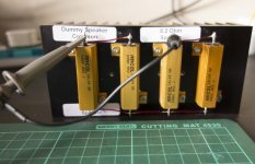
To this end I attached the scope probe to the amp output and the earth to the heatsink. the power leads (±) were disconnected but the xK amp ground (i.e. 0V) left in place.
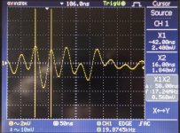
The pictures below show the set-up of the probe to kX amp and resulting 50 nS waveform.
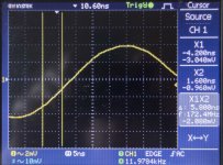
Based on this I simply attached the scope probe to the dummy load and get a very similar waveform which I've recorded at 5, 50 and 250 nS to get a better idea of the 'pulse' shape.
All the equipment (amp plus scope, frequency generator et all) is plugged into the same 'multiplug' which has a protection system. Other than the scope and amp all other equipment is off (including the amp PSU) except for the TV above this setup (I tried turning off the TV previously but it made no difference).
Any idea where this pulse might come from? i.e. what's generating it?
Could this waveform be creating/initiating the amp oscillation because it is almost identical frequency?
The probe itself was set at 1:1 and shorted was simply a 'flat line'.
Scope acquisition was set at 256 averaging
To this end I attached the scope probe to the amp output and the earth to the heatsink. the power leads (±) were disconnected but the xK amp ground (i.e. 0V) left in place.
The pictures below show the set-up of the probe to kX amp and resulting 50 nS waveform.
Based on this I simply attached the scope probe to the dummy load and get a very similar waveform which I've recorded at 5, 50 and 250 nS to get a better idea of the 'pulse' shape.
All the equipment (amp plus scope, frequency generator et all) is plugged into the same 'multiplug' which has a protection system. Other than the scope and amp all other equipment is off (including the amp PSU) except for the TV above this setup (I tried turning off the TV previously but it made no difference).
Any idea where this pulse might come from? i.e. what's generating it?
Could this waveform be creating/initiating the amp oscillation because it is almost identical frequency?
The probe itself was set at 1:1 and shorted was simply a 'flat line'.
Scope acquisition was set at 256 averaging
Attachments


Bonsai, I shorted out the two output transistors (+ and -) on the ripple eater and the oscillation is the same.
I had some similar 'oscillating pulses' at work. I'm not sure, but I think the scope has a switched supply that was somehow generating this, or there was some other switched supplies nearby for computers etc around (it's a a bit messy). Very low level, but disturbing when looking for those mV oscillations in the amp.
This doesn't look like the same problem Rocksteady has - yours is burst oscillation Tony, while his is continuous.
The only thing I can think of in your case is its rectifier turn off ringing with the wiring inductance and transformer leakage inductance, although its a bit high freq for that. You should see those HF bursts coming through every 10 milliseconds (100 Hz rectifier pulses). If they are, you can try a quick and dirty trick of a 0.05 to 0.1 uF cap right across the rectified AC terminals - its important to keep the leads short and right on the rectifier. If it is rectifier ringing, then you can put a proper snubber across the AC pins on the rectifier and that should cure it.
Might also be from your scope PSU as already suggested. Are you using a sign gen anywhere on your bench or any other mains powered stuff? LED lamp?
Rocksteady - you have a different problem. If you short the inputs, do you still have the problem?
For what it's worth, here are a few scope shots of the oscillation in my amp,
One is of 10 cycles and the other is zoomed way out.
If I'm understanding your problem, the oscillation is about ~6-7 MHz, right?
Are both channels doing this? If you short the inputs, what happens?
The oscillation is in both channels at 16 MHz with the inputs grounded or not, and with a load or not. Both channels seem to be working except for the oscillation.
“ I forgot to mention, and change in my schematics, I'm running lower gain, so R25 is 33ohm in my amp. Not that I think it should matter?”
In a CFA it is recommended to compensate the amp for a specific gain. The problem with this is your loop gain margin (this is the gain of the amps feedback loop directly below the point where the phase margin intersects 0 dB on the Bode plot) can be reduced when you decrease the gain which could then cause loop instability.
Since you reported very high oscillations (20 MHz), I don’t think this is your problem, but you should be aware of it. A VFA is usually bit more tolerant with gain changes like this.
Last edited:
Tony, if you turn the amp OFF do you still get the noise? I don’t understand the bit where you said you removed the +- leads - is this from your PSU?
Can you zoom out some more so I can see the time between the pulse bursts ie from one burst to the next? I’m getting the feeling your amp is not the problem here.
If you are getting these bursts from something external, or it’s line conducted, it will come right through the PSU - the filter caps, rectifiers etc will not block it due to circuit inductances and board capacitances as the frequency is very high at 17MHz.
If you unplug the PSU, but keep the scope connected what do you see?
Last edited:
Bonsai, I shorted out the two output transistors (+ and -) on the ripple eater and the oscillation is the same.
How are you powering your ripple eater and amp boards Rocksteady? From a track or a lab PSU?
Tony, if you turn the amp OFF do you still get the noise? I don’t understand the bit where you said you removed the +- leads - is this from your PSU?
Can you zoom out some more so I can see the time between the pulse bursts ie from one burst to the next? I’m getting the feeling your amp is not the problem here.
If you are getting these bursts from something external, or it’s line conducted, it will come right through the PSU - the filter caps, rectifiers etc will not block it due to circuit inductances and board capacitances as the frequency is very high at 17MHz.
If you unplug the PSU, but keep the scope connected what do you see?
I'll try and get some more components (SMD resistors + mica insulators) and do some more work today if I have time.
There is no waveform visible on the scope when the probe is shorted.
The scope for the amp was with PSU off and only the earth wire connected.
The waveform was also noted with just the scope connected across the dummy load as per the picture (amp PSU et al off)
In the first instance (amp) it might have pointed to earth 'garbage'
However the second instance (dummy load) would suggest it is a 'radiated' problem - although I guess this could be radiated from the earth wires.
When I first encountered this problem some months back I plugged in my JLH 15W amp within the same environment but there was no oscillation visible.
So I'll take the dummy load and scope to another room and see if the waveform is still visible.
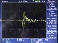
Meanwhile, attached is a 500 nS, time averaged screen capture from the kX with 'all systems running' for your comments
Cheers
Attachments

The only thing I can think of in your case is its rectifier turn off ringing with the wiring inductance and transformer leakage inductance, although its a bit high freq for that. You should see those HF bursts coming through every 10 milliseconds (100 Hz rectifier pulses). If they are, you can try a quick and dirty trick of a 0.05 to 0.1 uF cap right across the rectified AC terminals - its important to keep the leads short and right on the rectifier. If it is rectifier ringing, then you can put a proper snubber across the AC pins on the rectifier and that should cure it.
Should be easy to spot if you just scope the ac to the rectifier too I think.
Should be easy to spot if you just scope the ac to the rectifier too I think.
PSU is clean Rally.
Also the waveform is still there even with the PSU switched off 😕
Tony: Have you tried the same as I did and make a R+C+wire, connect one end to GND and just probe around to see where you get the best effect? You can also try connecting it to rails instead of GND.
Values may wary depending on where in the circuit you are. My guess would be maybe 100p + a few kOhms in the small signal stages, maybe 10n+100ohm for drivers/outputs?
Values may wary depending on where in the circuit you are. My guess would be maybe 100p + a few kOhms in the small signal stages, maybe 10n+100ohm for drivers/outputs?
Tony: Have you tried the same as I did and make a R+C+wire, connect one end to GND and just probe around to see where you get the best effect? You can also try connecting it to rails instead of GND.
Values may wary depending on where in the circuit you are. My guess would be maybe 100p + a few kOhms in the small signal stages, maybe 10n+100ohm for drivers/outputs?
I did originally but little change. haven't done it with the mods yet.
Do you not think this would impact on the slew rate though?
PSU is clean Rally.
Also the waveform is still there even with the PSU switched off 😕
It was the same for me, only way to get it quiet was to disconnect the probe GND.. Diff probe helped, but it has a lot of noise.
Did you jump the input to signal gnd at the connector on the PCB, or is the signal GND connected to something else too?
I did originally but little change. haven't done it with the mods yet.
Do you not think this would impact on the slew rate though?
It's more to pinpoint the problem area, to try to find the node most sensitive to the damping. How it affects performance depend on how it's implemented in the end. Simulation can help to show how it affects performance.
It was the same for me, only way to get it quiet was to disconnect the probe GND.. Diff probe helped, but it has a lot of noise.
Did you jump the input to signal gnd at the connector on the PCB, or is the signal GND connected to something else too?
Yes, all 3 input lines shorted together - line/ground/ shield. Wire length around 3 - 5 cm.
Originally had a longer coax cable (to go to signal generator) of around 50 cm which I shorted at the end when doing basic tests without input. Changed to the shorter one but made no difference to the oscillation.
Tony, you need to set the time base so we can see 2 or 3 of the bursts on the display, and then measure the time between them. We can then tell if it’s from 100 Hz diode switching or from a SMPSU where the rectifiers are causing ringing with the transformer.
Should be easy to spot if you just scope the ac to the rectifier too I think.
Problem is you have huge half wave pulses and that burst ringing is a few tens of mV at very high F and very short duration.
If you put a small resistor - say 50-100 ohms - in series with a 0.05uF cap across the rectifier terminals, you can pick up just the HF signal across the resistor.
But first let’s see what the noise source is in Tony’s case (then back to Rocksteady’s problem)
- Home
- Amplifiers
- Solid State
- Hifisonix kx-Amplifier