I have now changed to 68ohm and 300p, and it seems stable without zobel or load resistor. I my sim I also see some slight smoothing of a pole in the 20MHz area, so something is happening in that area according to sim too. Other than that, the loop seems unaffected.
Ordered some 330p and 69ohm resistors to tidy up the mod and make it more permanent. Would be interesting if somebody else tried this to see if it works for them. I tried 400p in simulation, and that even looked slightly better, so similar component values should do it.
I also measured distortion, and I still have the same problem with my measurement, but I think it has something to do with my Focusrite sound card, so I will try with my old ASUS sound card tomorrow which is good enough to confirm the amp is working as it should. Simulating it, I can't see any added distortion (FFT) with my mod.
@Bonsai: looking at the current through Q1 & Q2 in simulation, it's just over 200uA. Any specific reason for this?
it will help if for those who build it to see how many have that similar problem or none at all, and "not all build are the same" I'll wait for Bonsai annotation is there any changes on the schematic then I can go ahead with my diy design PCB from his schematic latest changes and completed, I'm gonna be on standby then 🙂
Attachments
I did some quick distortion measurements now, and all seems fine. Harmonics (H3 dominant) seem to stay at least 80dB down at different frequencies and output levels and input signals (sine/two sine/multitone) in low and high bias mode. Attached a multitone measurement with max output level on the sound card. Hard to define RMS on this type of signal..
I also tried R4 & R5 =1k (Q1 & Q2 running just over 1mA), but cant really see any difference in distortion. However, I think the square wave output (50kHz) looks a little nicer at high output using 1k resistors, so maybe stability is slightly improved. I have not tried with 1k resistors without the 300p+69ohm.
Let me add that my confidence in this amp has grown considerably now. Stability seems solid. I even tested with a 0,5uF cap parallel to the load at full output 50kHz square wave. Smoke from R3, but amp did not oscillate. Only deformed the square wave some.
Attachments
Last edited:
Looks like the problem is that the emitter follows in the top half of the VAS might be the culprit.
The resistor values are a bit different in both the sx and nx amplifiers.
Today I will return my amp to the original values and then look separately at their part of the circuit to see what I get.
It’s important to understand exactly how this mechanism is being triggered so it can be avoided in other designs.
My thanks to the work by everyone to solve it!
🙂
I just brought the prototype pair home for a listen, second song is playing now as I write.. I won't say anything about subjective impressions yet, because it's easy to draw conclusions too quick.
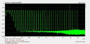
Both are now according to the schematic I posted above. I did some checks before bringing them home. No traces of oscillation. I also compared hum/buzz with and without the ripple eaters, and could not hear any hum even without ripple eaters, so I decided to run without them, see attached comparison FFT. I'm running dual mono, and 33mF caps per channel. Some spikes in the noise spectrum on the FFT, but it could just as well be due to my basic setup, long cables to sound card etc.
I'm running a 30Hz sine at high output in the FFT. I sometimes see modulation products with the PSU like this, but not in this case. Full bias.
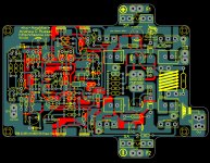
I also attach a picture of the prototype setup as it is now, I'm lucky to have a tolerant girlfriend! 🙂
Both are now according to the schematic I posted above. I did some checks before bringing them home. No traces of oscillation. I also compared hum/buzz with and without the ripple eaters, and could not hear any hum even without ripple eaters, so I decided to run without them, see attached comparison FFT. I'm running dual mono, and 33mF caps per channel. Some spikes in the noise spectrum on the FFT, but it could just as well be due to my basic setup, long cables to sound card etc.
I'm running a 30Hz sine at high output in the FFT. I sometimes see modulation products with the PSU like this, but not in this case. Full bias.
I also attach a picture of the prototype setup as it is now, I'm lucky to have a tolerant girlfriend! 🙂
Attachments

Last edited:
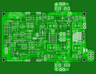
is there gonna be a schematic with the changes later? sorry that I ask this too many times I think Bonsai is working on that and he might be too occupied, I know Rallyfinnen is working on that too I'll stay in standby my layout is completed a few days ago so I be waiting then 
Attachments
I'm pretty sure Bonsai don't like my input mod, but I think he would agree on the changes around Q1 & Q2 (R45/46 & C18/19), and the extra cap (C17) in the bias circuit he already confirmed.
I think you could go ahead and add those while you wait for his investigation. Maybe he comes up with something else too.
I think you could go ahead and add those while you wait for his investigation. Maybe he comes up with something else too.
Last edited:
I’m just waiting for Tony to confirm my 1k resistor inserted into the collector of Q1 and Q2 fixes his problem.
Problem is my amp is not oscillating - so it’s difficult to solve this remotely, but we have to lock it down before closing off.
OPS - looks good
Current controller - looks good
Loop compensation also ok
Beta helper/VAS seems most likely.
Problem is, if you increase the collector current, it tends to make the problem worse (this is a generic issue with emitter followers - not just this specific case).
The emitter follower circuits form a Colpitts oscillator circuit structure with the parasitic components and that’s how you get this problem (see Bob Cordell for example and other sources).
The standard fix is to insert a base stopper of 50-100 ohms, but doing that here might interfere with the compensation and/or bias. The other solution is to put a damper resistor in the transistor collector. On the model I worked on today, just 1 nH in tne collector can make it oscillate. The 1k damper fixes this.
Vargasmongo, you need to wait until this issue is solved before ordering boards!
Last edited:
Hi Rallyfinnen...
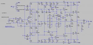
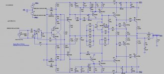
I looked at your modified KX amplifier scheme, you also changed the offset setting circuit, you added R44 with a value of 1ohm, it is a jumper to the power ground? The voltage for setting the offset in the original scheme was supplied to the connection R24 + R7 + R9 + C15 via R6, you otherwise connected R9 + R24 and the voltage for setting the offset is supplied via the R6 to the connection R9 + R24. With this connection, You has actually eliminated the purpose of the R9 resistor, it no longer fulfills the purpose of the HBR. R46 + C19 and R45 + C18 I understand why you added, but you also changed the values of R4, and R5 from 10k to 1k2? Why did you connect R8 to the Q10 emitter + R19 + R20 + R21 connection? In the original R8 scheme, the connection between Q5 emitter and R12 resistor. Thanks for the answers.
I looked at your modified KX amplifier scheme, you also changed the offset setting circuit, you added R44 with a value of 1ohm, it is a jumper to the power ground? The voltage for setting the offset in the original scheme was supplied to the connection R24 + R7 + R9 + C15 via R6, you otherwise connected R9 + R24 and the voltage for setting the offset is supplied via the R6 to the connection R9 + R24. With this connection, You has actually eliminated the purpose of the R9 resistor, it no longer fulfills the purpose of the HBR. R46 + C19 and R45 + C18 I understand why you added, but you also changed the values of R4, and R5 from 10k to 1k2? Why did you connect R8 to the Q10 emitter + R19 + R20 + R21 connection? In the original R8 scheme, the connection between Q5 emitter and R12 resistor. Thanks for the answers.
I wanted the offset adjustment to be applied to the input, not the signal gnd. It does not matter much in dual mono, but with single supply, connecting both signal gnd's to the common ground of the source will change the offset adjustment. I wanted this out of the equation.
I saw lower noise when bypassing R44 with a cap earlier, so I used a 1ohm resistor as a jumper 😉 Things might be different using single supply. HBR should not be needed in dual mono, since there is no ground loop via power GND IMHO.
R4-5: As I mentioned earlier, I tried it and compared the square wave response, and it was a little bit cleaner on high output with the lower value. I thought the Q1-2 current was a bit low(?), and impedance in the circuit high, my thinking was that lower impedance would be less sensitive to Cob etc. so I wanted to try it, and it looked a little bit better on the flanks, and distortion was the same, so I thought why not. Now Q1&2 are at abt 1mA, was just over 0,2mA before.
R8 is a mistake in the posted schematic. I did not change it from the original, sorry about that one! I have several sims, and have been playing around with different things on different sims.. hard to keep track of everything 🙂
Last edited:
I think running Q1 and Q2 at higher current is a good thing so no issues there.
The main thing now is to make a fix that is robust and supported by simulation to some extent. As I mentioned, an emitter follower can be problematic. I only ever had this kind of problem in the e-Amp and then on one of my commercial amps in cascode stages ( because I failed to follow the rules - but I caught this in development so no big deal).
This problem is quite subtle so it has taken time.
Again, I appreciate everyone’s input. Thank you.
Last edited:
Rallyfinnen
Thx so much for Your quick answer, now its clear to my, why You changed the offset circuit...because of dual mono...and the error in the schema..."Who does nothing, will do not make a mistake"....Best Regards
Thx so much for Your quick answer, now its clear to my, why You changed the offset circuit...because of dual mono...and the error in the schema..."Who does nothing, will do not make a mistake"....Best Regards
I’m just waiting for Tony to confirm my 1k resistor inserted into the collector of Q1 and Q2 fixes his problem.
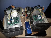
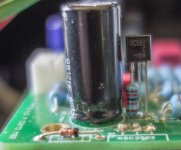
I managed to get this done this morning but using 1K2 resistors (I don't have 1/4 W smaller than 1/2 W - and it would be too big) and mounted them in both collector leads, using new transistors, as per the attached photo.
Unfortunately the oscillation at 17MHz is still there 🙁
The board is 'standard' other than 100nF caps across C9/C14 'under board' and the ZN is connected directly to the board.
With an 8 ohm dummy load attached the oscillation measures 135 mV RMS
Without the dummy load 233 mV RMS
Supply lines are ±32V, input shorted and running in AAB mode.
Work continues.
Attachments
Did you add R45/C18 & R46/C19 as in my schematic? This is what fixed it for me.
Values are not critical, just something close enough should do, I'm guessing 300-500p and 50-150ohm.
The lower value on R4 & R5 was just 'icing on the cake' to increase the current a bit, did not make much difference other than a little bit nicer square wave flanks.
Values are not critical, just something close enough should do, I'm guessing 300-500p and 50-150ohm.
The lower value on R4 & R5 was just 'icing on the cake' to increase the current a bit, did not make much difference other than a little bit nicer square wave flanks.
- Home
- Amplifiers
- Solid State
- Hifisonix kx-Amplifier